Press fit looks like one of the simplest assembly methods: push one part into another, and the joint is done. But behind that simple motion is careful control of dimensions, tolerances, and material behavior — get them wrong, and the joint can require excessive force to assemble or fail to provide enough holding strength. This article walks through the process in plain terms and clears up a few commonly confused concepts along the way.
What Is a Press Fit?
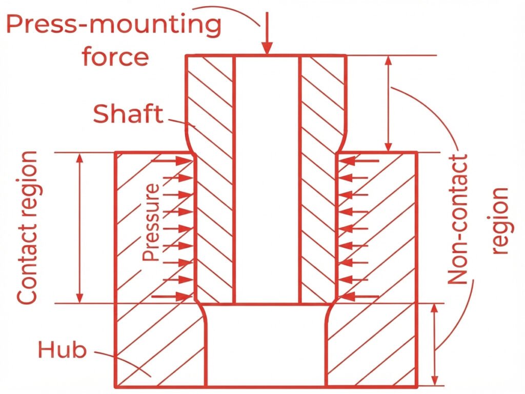
A press fit is an assembly method that joins two parts through mechanical force alone, rather than fasteners, adhesives, or welding. One part is pressed directly into or onto another — a pin into a plate, a bushing into a housing, or a sleeve over a shaft — and the resulting contact pressure and friction at the mating surfaces hold the assembly together.
Press Fit vs. Interference Fit
Interference fit is not an assembly method — it is a dimensional relationship between two mating parts, where the mating dimensions intentionally overlap before assembly. This size difference, called interference, is what generates the contact pressure holding the joint together once the parts are mated.
Press fit is one way of realizing that relationship in practice: applying axial force to push one oversized mating feature into another, relying mainly on elastic deformation of the parts to accommodate the interference. But it is not the only way.
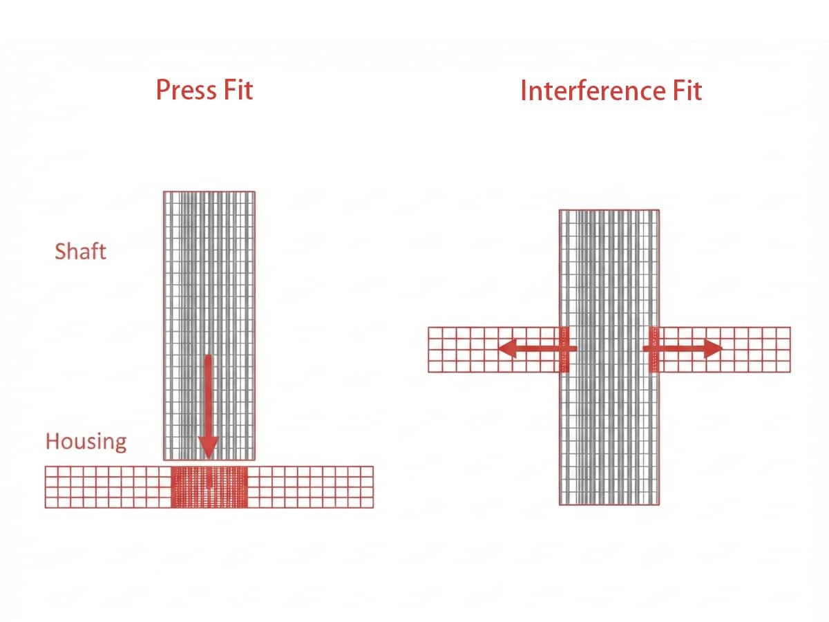
So every press fit joint relies on interference, but not every interference fit is created by pressing. Press fit describes how the joint is assembled; interference fit describes the dimensional condition that makes the joint possible.
How to Determine the Interference for a Press Fit
The shaft-and-hole pair is the most intuitive example to work through, so we’ll use it here. Assume the joint needs an interference fit: the shaft must transmit torque and stay in place permanently.
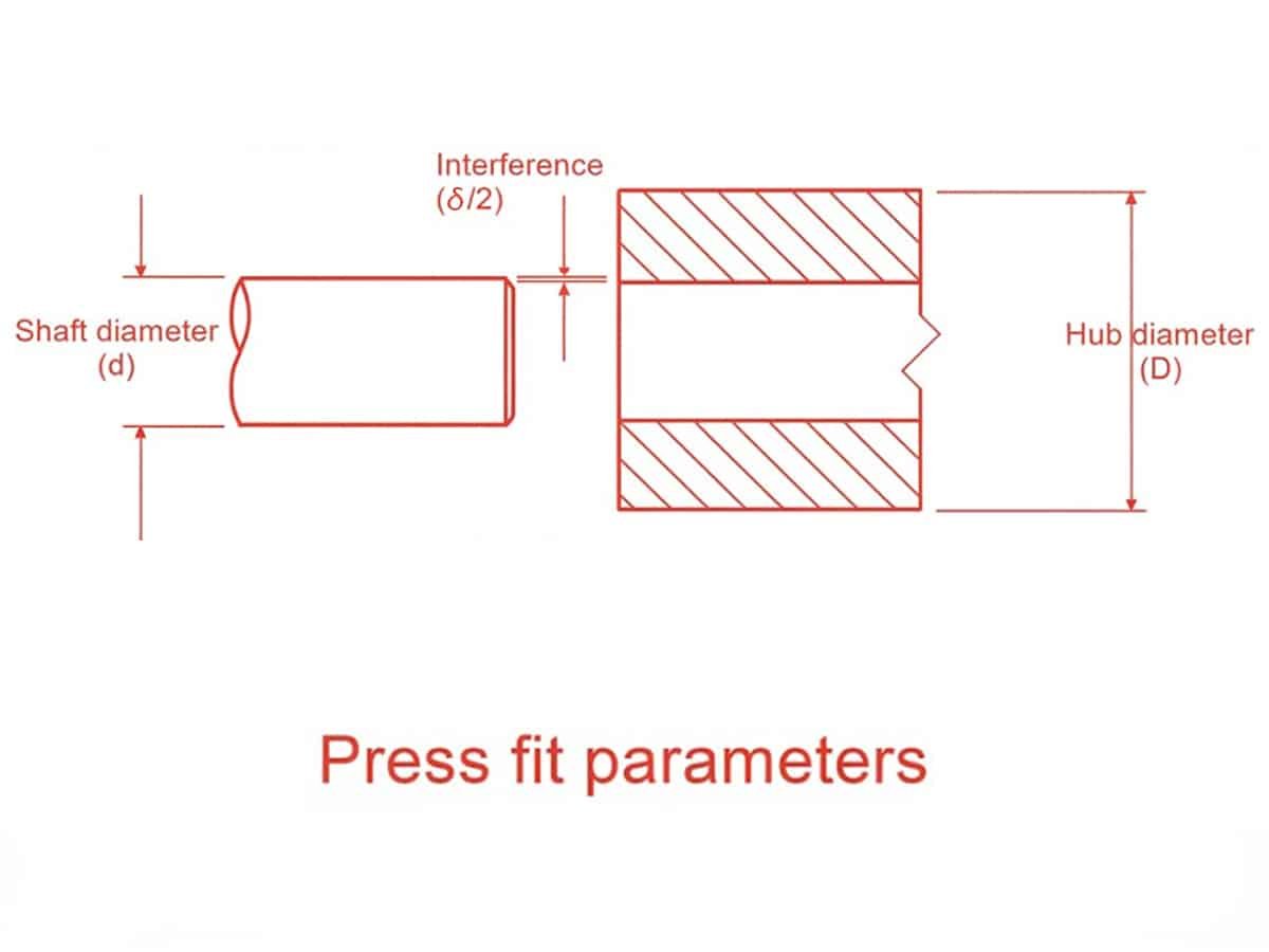
Before any interference is calculated, the functional requirement, part geometry, and material are already fixed. Say the shaft is solid steel, 25 mm in diameter, fitting into a steel hub with a 50 mm outer diameter.
The Formula
For a simplified steel-on-steel press fit with a solid shaft, the contact pressure generated by an interference δ can be estimated as:
p = Eδ / [d(1 + K)]
where:
- p = contact pressure
- E = modulus of elasticity
- d = shaft diameter
- δ = diametral interference
- K = geometry factor:
K = (D²+d²) / (D²−d²)
where D is the hub’s outside diameter.
K accounts for the effect of hub geometry on radial expansion. The hub wall thickness changes how much the interference is converted into contact pressure.
For a 25 mm steel shaft inside a 50 mm steel hub:
K = (50² + 25²) / (50² − 25²) = 3125 / 1875 ≈ 1.67
With E=200000MPa:
p≈3000δ
This means each 0.01 mm of diametral interference produces approximately 30 MPa of contact pressure in this simplified case.
Setting the Range
Minimum interference
Minimum interference is determined by the required holding force.
Assume the required torque capacity corresponds to a minimum contact pressure of 45 MPa:
δ_min = 45 / 3,000 = 0.015 mm
Maximum interference
Maximum interference is limited by the allowable stress in the hub.
Using the simplified relationship:
σ_h≈pK
where:
- σ_h = hoop stress at the hub bore
- K = geometry factor
Assume the allowable hoop stress is 175 MPa:
p_max = 175 / 1.67 ≈ 105 MPa
Then:
δ_max = 105 / 3,000 = 0.035 mm
The resulting target interference range is therefore: 0.015–0.035 mm.
Selecting a Tolerance Class
A range like this can’t be machined as an exact number — every shaft and hole carries its own manufacturing tolerance. So the next move is to translate the target into a standardized tolerance class, one that’s actually achievable on a shop floor.
Most press fits use the hole-basis system: the hole is held to a fixed zone, commonly H7, and the shaft’s zone is varied to set the interference.
| ISO Designation | Interference Level | Typical Use |
|---|---|---|
| H7/p6 | Light | Accurate location, lightly loaded hubs |
| H7/r6 | Moderate | Gears, shaft-mounted parts |
| H7/s6 | Higher | Permanent, higher-load joints |
| H7/u6 | Heavy | Highly loaded joints, often shrink fit |
Given the target range above, something in the H7/s6 territory looks like the right starting point.
Verifying the Actual Range
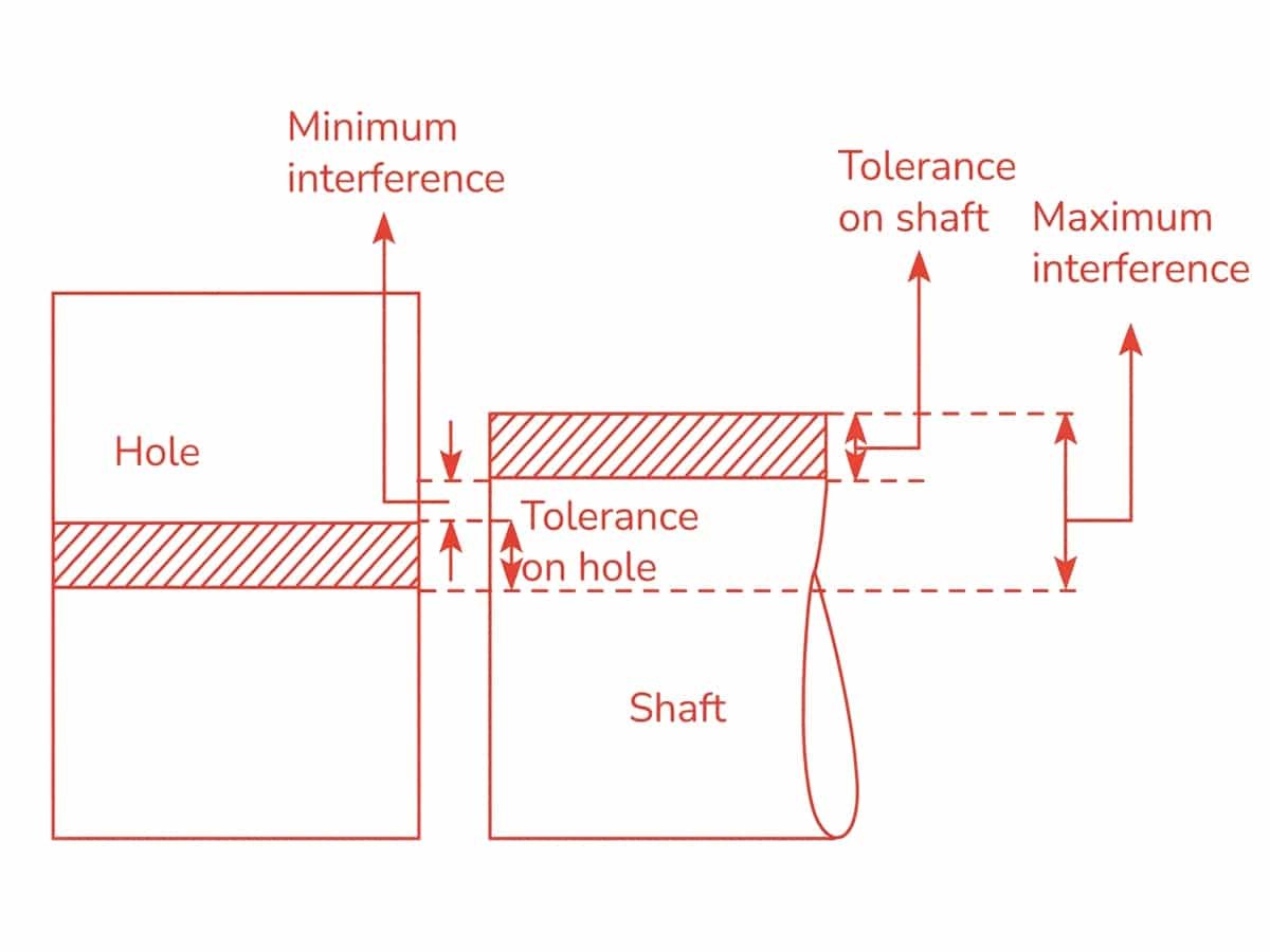
Assume a 25 mm H7/s6 fit produces:
- H7 hole: 25.000–25.021 mm
- s6 shaft: 25.035–25.048 mm
Minimum interference:
25.035 − 25.021 = 0.014 mm
Maximum interference:
25.048 − 25.000 = 0.048 mm
Therefore:
- Actual minimum: 0.014 mm
- Actual maximum: 0.048 mm
Compared with the target:
- Required: 0.015–0.035 mm
- Actual: 0.014–0.048 mm
The fit is slightly outside the target window:
- The minimum interference is marginally insufficient.
- The maximum interference exceeds the allowable limit.
If the Range Doesn’t Fit
When the actual range misses the target, the fix usually starts small: try an adjacent tolerance class before touching anything upstream. H7/r6 undershoots the load requirement even further; H7/u6 overshoots the stress limit even more than s6 does.
If nothing in the standard table lands inside the target window, the problem isn’t the tolerance class — it’s further back. That means returning to the material and geometry chosen earlier: a thicker hub lowers the stress from a given interference, a different material shifts the modulus, and either changes what the target range needs to be in the first place.
How to Achieve a Press Fit joint
Once the interference and tolerance requirements are established, the next step is to determine how the parts will be assembled. The method must provide enough force or dimensional change to achieve the fit while avoiding damage, excessive stress, or impractical equipment requirements.
Mechanical Pressing
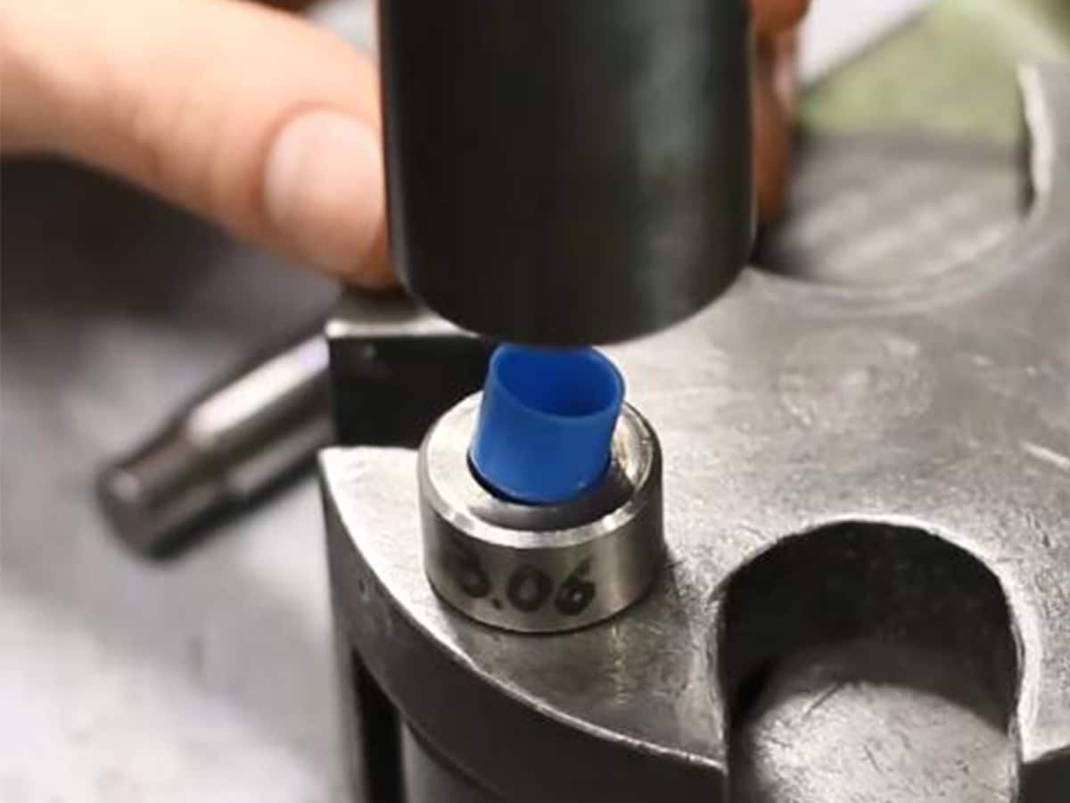
Axial force pushes the shaft into the hole while both parts stay near their normal dimensions. Arbor presses handle light work; hydraulic or servo presses provide the force and control needed for larger or higher-interference joints.
Thermal Assembly
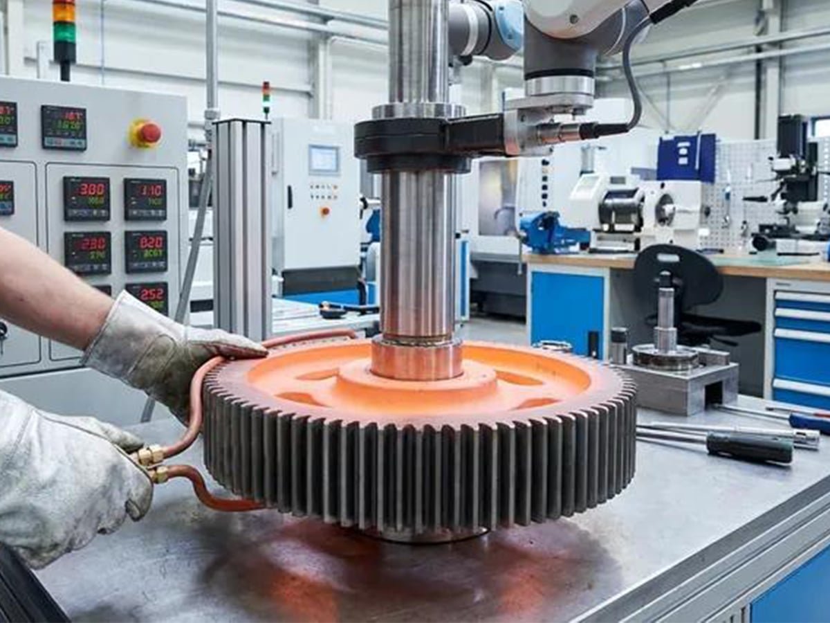
Heating the hub (shrink fit) or cooling the shaft (cold fit) temporarily changes its size, letting the parts slide together with little or no force. Combining both allows for larger interference values than mechanical pressing alone.
Hydraulic or Oil-Injection Mounting
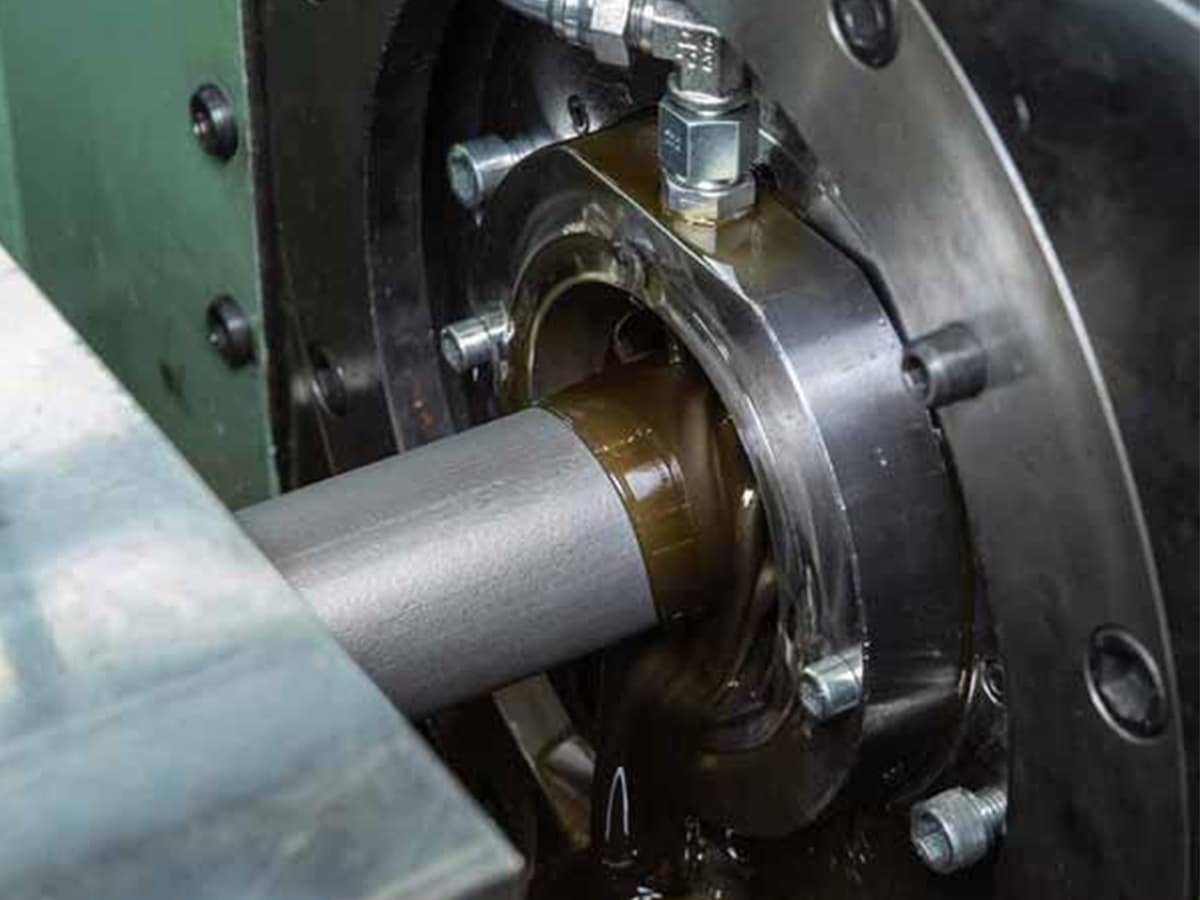
Pressurized oil at the interface reduces friction, allowing assembly under much lower force. It’s typically reserved for large-interference joints and heavy industrial assemblies where mechanical pressing isn’t practical.
Factors Affecting Press Fit Connection Performance
The calculations above determine the target range, but several practical factors sit outside that math and still shape whether the joint performs well.
Lead-In Geometry
Chamfers and pilot features let the shaft begin engaging before full interference develops, reducing damage and force spikes at first contact. Without them, the leading edge can scrape and damage the mating surfaces.
Assembly Speed
Pressing speed affects how smoothly the parts seat and how well the process can be controlled. Excessive speed can increase frictional heating and galling risk, especially with similar or softer materials, while controlled speeds improve consistency.
Surface Finish
Surface roughness affects actual contact conditions after assembly. Rough surfaces can deform during pressing, changing friction behavior and assembly force. Excessive roughness increases galling risk, while overly smooth surfaces or heavy lubrication can reduce friction and retention.
Temperature
Dissimilar materials expand at different rates. A fit that holds at room temperature can loosen or generate excessive stress at operating temperature if thermal expansion is not considered.
Creep and Stress Relaxation
Polymers, elastomers, and some low-strength materials can gradually relax under sustained contact pressure, reducing retention over time. This matters most for permanent joints expected to hold without maintenance.
Common Problems and Solutions
Some problems only appear after assembly. The most common issues and their likely causes include:
- Joint too loose / slips under load — Actual interference may fall below the target minimum. Verify the tolerance class and consider a higher-interference fit.
- Excessive press-in force — Often caused by excessive interference, long engagement length, or poor lead-in geometry. Reduce interference, shorten engagement, or add chamfers.
- Galling or scoring on mating surfaces — Usually caused by high friction, rough surfaces, or misalignment. Improve surface finish, alignment, or lubrication.
- Interference varies between parts — Manufacturing variation, coatings, or plating can shift final dimensions. Measure finished mating surfaces before assembly.
- Joint loosens over time — Creep and stress relaxation, especially in polymers and elastomers, can reduce retention. Use more suitable materials or adjust the interference range.
Conclusion
Getting the interference right starts with calculation, but achieving a reliable force fitting requires consistent machining and controlled assembly. Zhongde CNC machining services produce tolerance-critical shafts, hubs, and mating components, with DFM support and assembly capabilities available for complete part production.