In industrial manufacturing, most people understand that complex machines and equipment are made up of many individual components. However, few stop to consider exactly how these parts come together—you can’t rely on glue or screws to solve every connection problem.
The reality is that the way components are joined often determines whether a device operates smoothly, performs as intended, and lasts over time. This is where the concept of a fit becomes important—because in engineering, the quality of an assembly is often defined long before the machine ever starts operating.
What Is a Fit?
In manufacturing, a fit describes how two mating parts—typically a shaft and a hole—come together. Think of it as the “relationship” between components: will they slide together freely, align precisely, or lock firmly in place? The fit determines not only how easily parts can be assembled, but also how they behave under operational forces, vibration, and wear.
For example, in a motor assembly, the shaft must rotate smoothly inside a bearing without wobbling, while still remaining securely in position. The precise choice of fit ensures that the shaft doesn’t rattle or seize during operation. In another case, a press-fit gear on a steel shaft must hold tightly under torque without slipping. These real-world scenarios show why understanding and selecting the right fit is crucial: it directly affects the performance, durability, and safety of the final product.
In essence, a fit is more than just a measurement—it’s a critical engineering decision that balances assembly ease with operational reliability.
Hole Basis System vs Shaft Basis System
In manufacturing, engineers use standardized approaches to define how parts are paired together. The two most common systems are the hole basis system and the shaft basis system, which describe which component—the hole or the shaft—is kept as the reference for sizing.
In a hole basis system, the hole is treated as the fixed reference, and the shaft size is adjusted to achieve the desired assembly performance. This method is often used because holes are usually more difficult to modify after machining, especially in components like bearing housings or precision housings. By controlling the shaft size, engineers can ensure that the part slides, locates, or locks as intended.
Conversely, in a shaft basis system, the shaft is the fixed reference, and holes are sized around it. This system is less common but useful when shafts are standardized, stock components—such as precision rods used across multiple assemblies. Adjusting the hole dimensions allows designers to achieve the appropriate fit for different assembly requirements.
Both approaches serve the same purpose—controlling how two parts come together—but they differ in which component is treated as the starting point in manufacturing.
Fits and Tolerances: What’s the Relationship
At this point, we already know that fits describe how two parts—such as a shaft and a hole—come together in an assembly. But in real manufacturing, the question is: how do engineers actually control whether a part fits tightly, loosely, or somewhere in between?
This is where tolerances come in.
A tolerance defines the acceptable variation in a part’s dimension during manufacturing. No machining process can produce perfectly identical parts every time, so small variations are always expected. Tolerances set the allowable range for these variations.
In engineering drawings, tolerances are often expressed using standardized notation. Uppercase letters usually represent holes and lowercase letters represent shafts. The number that follows indicates the tolerance grade, or how tightly the dimension is controlled. For example, H7 refers to a hole with a medium tolerance range, while h6 indicates a shaft with a slightly tighter tolerance. When a shaft h6 fits into a hole H7, the result is a predictable clearance fit.
Three Types of Fits and Their Grades
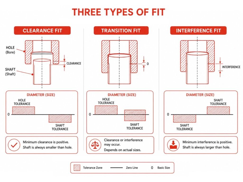
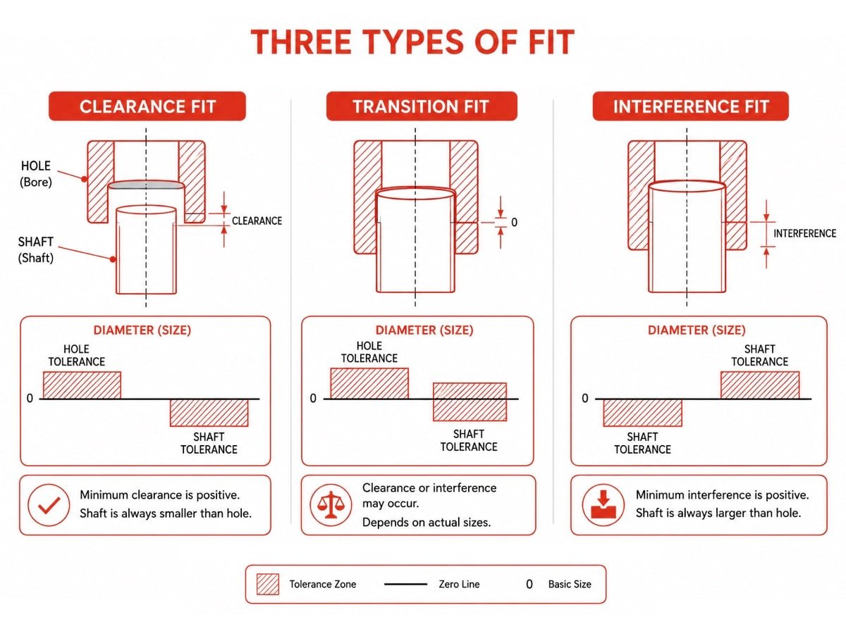
In engineering practice, fits are generally divided into three main types based on how tight or loose the connection between two mating parts is. These are clearance fits, transition fits, and interference fits. Each category is further divided into specific grades that describe the exact degree of looseness or tightness in the assembly.
Clearance Fits
A clearance fit means there is always a gap between the shaft and the hole, even at their largest and smallest manufacturing limits. In other words, the shaft is always smaller than the hole, allowing movement or easy assembly.
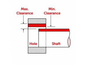
The maximum clearance is the largest possible gap, while the minimum clearance is the smallest gap that still allows assembly. Clearance fits are ideal for components that need to move or rotate freely without binding.
- Loose Running Fit – Provides a relatively large clearance, used in low-load rotating parts such as shafts in simple conveyor rollers where smooth assembly is more important than precision.
- Free Running Fit – A moderate clearance often seen in pump rotor shafts or low-load motor shafts, where continuous rotation is required without resistance.
- Close Running Fit – A smaller clearance used in precision spindle systems or machine tool auxiliary shafts, where motion must remain stable with minimal play.
- Sliding Fit – Designed for controlled linear motion, commonly used in linear guide rails or adjustable fixture components in CNC machines.
- Locational Clearance Fit – Used in assembly alignment features such as positioning pins in machine housings, where accurate location is required but parts must still be removable.
Interference Fits
At the opposite end of the spectrum, interference fits occur when the shaft is slightly larger than the hole, meaning assembly requires force or pressing. Once assembled, the parts remain tightly locked together.
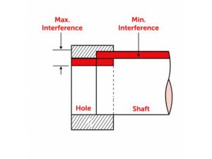
The maximum interference defines the tightest assembly, while the minimum interference ensures the part is still forceable into place. Interference fits are commonly used where parts must stay fixed under load or torque.
- Driving Fit – Used in applications like gear hubs mounted on transmission shafts, where torque must be transmitted without slippage.
- Forced Fit – Common in pulley or coupling installations on industrial motor shafts, requiring mechanical pressing during assembly.
- Press Fit – Used in permanent assemblies such as steel pins inserted into structural machine frames, where disassembly is not normally intended.
Transition Fits
Transition fits occupy the middle ground between clearance and interference. Depending on the actual dimensions after manufacturing, the assembly may result in either a small clearance or a slight interference. Transition fits are often chosen when parts must be accurately positioned without requiring excessive assembly force, for example, in gearboxes or precision frames.
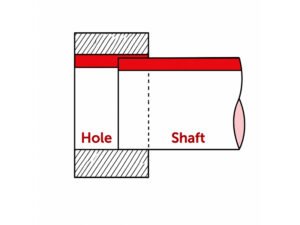
- Similar Fits – Used in precision alignment features such as dowel pins in gear housings, where positioning accuracy is important but assembly force remains moderate.
- Fixed Fits – Used in semi-permanent assemblies such as bushings in machine supports, where parts must stay firmly in place but may still be removed during maintenance.
How to Choose the Proper Fit
With three types of fits and more than a dozen specific grades to choose from, a natural question arises: how does an engineer actually decide which fit is right for a given application? The answer is rarely a single factor. In practice, the right fit emerges from weighing several considerations together—function, load, assembly method, material, and cost. Working through each one systematically helps narrow the options and avoid costly mistakes.
Start With the Functional Requirement
The most important question to ask is also the simplest: what does this assembly need to do? A component that must rotate or slide continuously needs room to move—that points toward a clearance fit. A part that must stay permanently locked under torque or vibration needs to be held in place—that calls for an interference fit. And when accurate positioning matters but occasional disassembly is expected, a transition fit often strikes the right balance.
Defining the function first prevents over-engineering or under-specifying—both of which carry real consequences on the shop floor and in the field.
Consider the Forces and Loads Involved
Once the function is defined, the next step is to examine the operating conditions. Parts exposed to heavy torque, shock loading, or continuous vibration require tighter fits to prevent relative movement between mating surfaces. Components under light or purely axial loads can often tolerate wider clearances without compromising reliability.
A drive gear on a high-torque industrial gearbox, for instance, typically demands a driving or press fit to prevent fretting and slippage—while an idler gear on a low-load shaft may perform reliably with nothing tighter than a close running fit.
Think About Assembly and Disassembly
It’s easy to focus on how a part performs in operation and overlook how it will be put together—or taken apart. Yet this is a practical constraint that can rule out certain fit choices entirely.
Interference fits create permanent or semi-permanent connections that require mechanical presses or heat treatment to assemble, and they are difficult to disassemble without risking damage to the components. If a part needs to be removed during routine maintenance or field servicing, a transition or clearance fit is almost always the more practical choice, even if it means accepting slightly less holding force.
Factor in Material Properties
Two parts may be dimensioned correctly on paper, yet still behave unexpectedly once in operation—often because material properties weren’t fully accounted for. Metals with high thermal expansion coefficients, such as aluminum, can shift from a clearance condition to an interference condition as temperatures rise during use. Softer materials may deform permanently under the stress of a tight interference fit.
This means fit selection cannot be based on room-temperature dimensions alone. Engineers must consider both the elastic modulus and the thermal behavior of each material to ensure the assembly remains functional across its full operating range.
Balance Precision Against Manufacturing Cost
Tighter fits require tighter tolerances—and tighter tolerances require more precise machining, more rigorous inspection, and higher production costs. A tolerance grade of IT5 or IT6 demands significantly more process control than IT8 or IT9, and not every facility can achieve it consistently or economically.
This is why over-specifying fit tightness is one of the most common and costly errors in engineering design. As a practical rule: specify only as tight a tolerance as the application genuinely requires. Unnecessary precision adds cost without adding value.
Use Standards as a Starting Point
Finally, it is worth noting that engineers rarely design fits entirely from scratch. International standards such as ISO 286 provide comprehensive tolerance tables and recommended fit combinations validated across thousands of real-world applications. Standard pairings—such as H7/g6 for a free running fit or H7/p6 for a press fit—give designers a reliable, proven foundation to build from, rather than recalculating from scratch each time.
Conclusion
From understanding what a fit is, to selecting the right type for a specific application, it is clear that fit specification is far more than a footnote on an engineering drawing. It is a foundational decision that shapes how a machine performs, how long it lasts, and how reliably it can be assembled and maintained. If you have read this far, you already have a stronger grasp of this topic than most.
Of course, even the most carefully chosen fit specification is only as good as the parts that are actually produced. With extensive experience in custom molded parts service, Zhongde offers a fully integrated, one-stop process—from design consultation and material selection through to final production. Whether you are sourcing a single prototype or scaling up to full production, get in touch with Zhongde to discuss how we can bring your specifications to life.