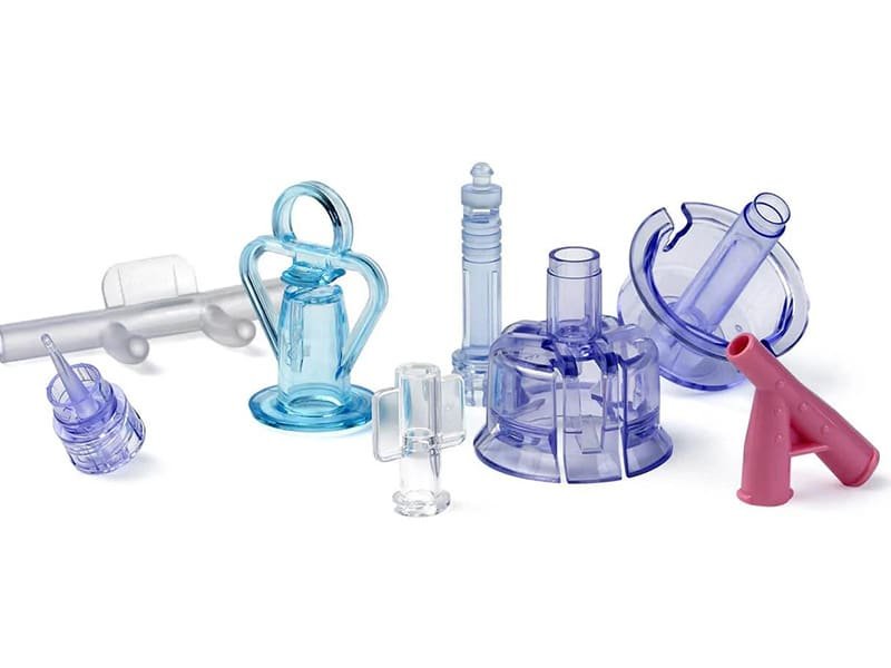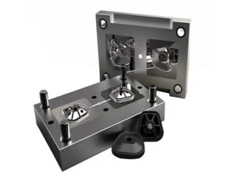
Many people tend to think of molds as simple tools used to shape materials into parts. In industrial manufacturing, however, mold tooling is more closely integrated with the entire production process, playing a key role in determining product quality, consistency, and efficiency.
In this guide, we will focus on mold tooling with a strong emphasis on injection mold tooling—covering its structure, design considerations, manufacturing process, cost factors, and common issues. We will also briefly introduce other types of plastic molds to provide a more complete understanding.
What Is Mold Tooling?
When we talk about tooling, it often refers to production tools such as molds and dies. In simple terms, molds are commonly used to shape plastic materials, while dies are more often associated with metal forming processes.
A mold can be understood as a tool used to shape and solidify molten plastic into a desired form. In one of the most common molding methods, molten plastic is injected into a mold cavity, cooled, and then ejected as a finished part—a process known as injection molding.
With this distinction in mind, it becomes easier to understand why the term mold tooling is so often associated with injection mold tooling. However, injection molds are only one type of plastic mold. Other plastic molding processes also use molds, such as compression molding, blow molding, and casting. In this guide, we’ll start with injection molds, as they are the most widely used and form the core of modern plastic manufacturing.
Why Mold Tooling Is Important
Why is mold tooling so important in manufacturing? If we look at a finished plastic part, it is easy to focus only on the material or product design. But in reality, the quality of that part is largely defined long before production starts—at the tooling stage.
You can think of mold tooling as the “foundation” of a production system. Just like the accuracy of a building depends on its foundation, the consistency and precision of manufactured parts depend heavily on how the mold is designed and built. Even small variations in tooling can lead to noticeable differences in part quality during mass production.
From a production perspective, well-designed tooling can significantly improve efficiency. A stable mold helps shorten cycle times, reduce defect rates, and maintain consistent output over long production runs. In contrast, poor tooling design can quickly lead to issues such as dimensional variation, surface defects, or unstable production.
It also plays a decisive role in product feasibility. Some design features may look simple on paper but are difficult to achieve in mass production without proper tooling support. This is especially true in injection molding, where high precision and repeatability are often required.
Types of Common Injection Molds
If injection molding follows the same basic principle of injecting material into a mold, why are there still so many mold types?
The reason is simple: different products require different mold designs. Production volume, part complexity, assembly requirements, and material combinations can all influence which mold type is most suitable.
Below are some of the most common injection molds used in plastic manufacturing. To dive deeper into this topic, check out our detailed guide on A Guide for Injection Mold Classification and Types.
Single-Cavity Mold
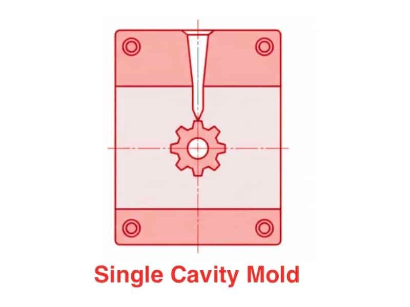
A single-cavity mold produces one part in each injection cycle. It is commonly used for low-volume production, prototype development, or large parts that require significant mold space. While production efficiency is lower, this type offers simpler mold design and easier process control.
Multi-Cavity Mold
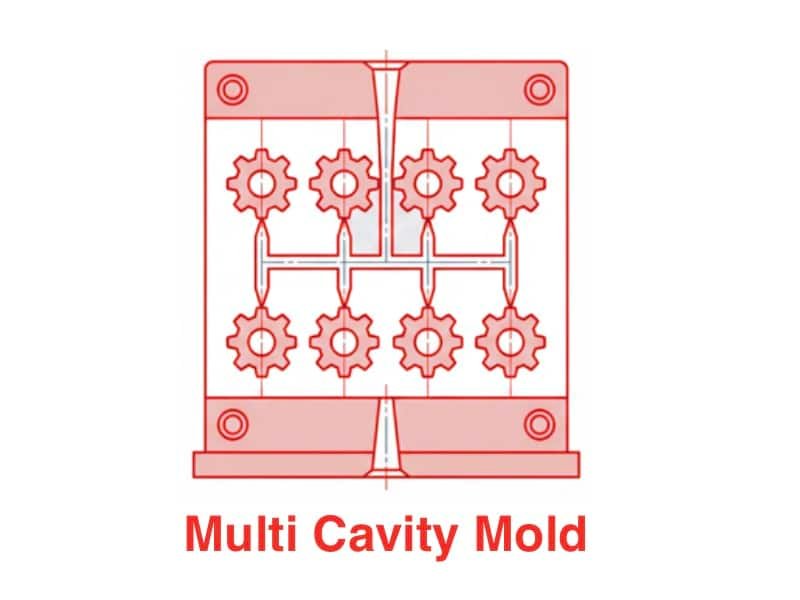
A multi-cavity mold produces multiple identical parts in one cycle, making it ideal for mass production. Since plastic must fill several cavities at once, runner balance, pressure distribution, and cooling consistency are critical to maintaining uniform part quality.
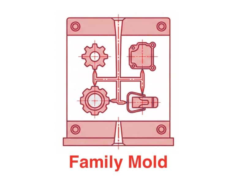
Family Mold
A family mold includes multiple different cavities within the same mold, allowing related parts to be molded together in one cycle. It is often used when several components belong to the same assembly. Since different parts may vary in size, wall thickness, or filling behavior, balancing material flow and controlling shrinkage can be more challenging than in standard multi-cavity molds.
Stack Mold
A stack mold is designed with multiple parting levels, effectively increasing the number of cavities within the same mold footprint. It is commonly used for high-volume production where space efficiency and output are important. Because melt flow, clamping force, and part ejection must be controlled across multiple molding levels, stack molds usually require tighter structural alignment and more advanced tooling design.
Insert Mold
Insert molds are used to encapsulate a pre-placed component—often metal, ceramic, or another rigid insert—inside molded plastic. This process helps improve mechanical strength and can reduce secondary assembly work. Since the insert must remain accurately positioned during injection, insert stability, mold alignment, and material bonding become key design considerations.
Overmolding Mold
Overmolding molds are used to mold one material over an existing substrate, creating a single integrated part. This is commonly used to combine rigid and soft materials, improve grip, add sealing features, or enhance product functionality. Because two materials must bond properly without affecting dimensional accuracy, substrate positioning, adhesion compatibility, and process control are especially important.
Key Injection Mold Components
An injection mold is made up of several precision-engineered components that work together to form, cool, and eject plastic parts. While mold designs may vary depending on application, most injection molds share a similar structural foundation.
Mold Base
The mold base is the supporting structure that holds all components together. It provides alignment, stability, and mounting support during the injection process, ensuring that the mold operates under high pressure without deformation.
Cavity and Core
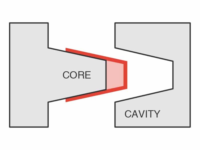
The cavity and core form the shape of the final product. The cavity defines the external surface, while the core forms the internal geometry. Their precision directly determines part accuracy, surface quality, and dimensional consistency.
You can also learn more about cavity and core in our guide on Everything You Need to Know About Core and Cavity in Injection Molding.
Runner System
The runner system guides molten plastic from the injection nozzle into the cavity. Its design affects material flow balance, filling efficiency, and pressure distribution, especially in multi-cavity molds.
Gate
The gate is the entry point where molten plastic enters the cavity. Its size and location influence flow behavior, weld lines, and surface appearance of the final part.
Ejection System
The ejection system is responsible for removing the finished part from the mold after cooling. It typically includes ejector pins or plates, and must be carefully designed to avoid deformation or surface damage.
Cooling System
The cooling system controls mold temperature during production. Efficient cooling design helps reduce cycle time, improve dimensional stability, and prevent defects such as warping or shrinkage.
Curious how cooling system can influence part quality? Learn more in our article on Injection Molding Cooling Systems: Methods and Design.
Tooling Design Factors
What makes a mold design successful? Is it just about shaping a part correctly, or does it also need to ensure stable production over thousands—or even millions—of cycles? In practice, mold tooling design is a balance of multiple engineering factors that directly affect part quality, production efficiency, and long-term reliability.
Below are some of the key design considerations in injection mold tooling.
Part Geometry and Manufacturability
Before a mold is even built, one of the first questions engineers ask is: Can this part actually be manufactured efficiently? Complex geometries may look simple in CAD, but they can introduce undercuts, uneven wall thickness, or difficult demolding conditions.
You can think of it like designing a path for water flow: the more turns, obstacles, or narrow sections you add, the harder it becomes to maintain stable and consistent movement.
Wall Thickness Control
Wall thickness directly influences how a part fills and cools inside the mold. Uneven thickness can lead to defects such as sink marks, warping, or incomplete filling.
A useful way to understand this is to imagine pouring melted chocolate into a mold: thicker areas take longer to solidify, which can disrupt the overall shape if not properly balanced.
Draft Angle Design
If a part sticks inside a mold, what happens next? In production, even a small demolding issue can interrupt the entire cycle.
Draft angles solve this problem by slightly tapering vertical surfaces, allowing parts to be ejected smoothly. Without proper draft design, the mold behaves like a tight-fitting container that becomes harder to release with every cycle.
Gate Location and Flow Control
Where the molten plastic enters the cavity can change everything. A poorly placed gate can lead to weld lines, air traps, or uneven filling.
It helps to imagine the cavity as a network of roads—if the entry point is poorly positioned, traffic (material flow) becomes unbalanced, leading to congestion in some areas and shortages in others.
Cooling System Layout
Cooling is one of the most critical but often underestimated parts of mold design. It directly affects cycle time and dimensional stability.
Efficient cooling channels help the part solidify evenly. Poor cooling design can be compared to uneven heating in cooking—it may produce the right shape, but not the right quality.
Ejection Strategy
After cooling, the part must be removed from the mold without damage or deformation. This requires careful design of ejector pins, plates, and release angles.
You can think of this step as removing a finished product from a precise frame—if the force is uneven or poorly distributed, the part can easily be marked or distorted.
The Injection Mold Tooling Manufacturing Process
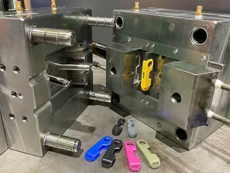
How is an injection mold actually made? While the final mold may look simple from the outside, its manufacturing process involves multiple precision engineering steps, each of which directly affects the performance and lifespan of the tool.
Design and DFM Analysis
Every mold begins with design. Before any steel is cut, engineers evaluate the part structure, material behavior, and manufacturability.
This stage is often where potential issues are identified. Can the part be ejected smoothly? Will the material flow evenly? Are there risks of warping or shrinkage? These questions are addressed through DFM (Design for Manufacturing) analysis.
In many cases, good design decisions here determine the success of the entire project.
Mold Material Selection
Not all molds are built from the same material. Different steel grades are selected based on production volume, plastic type, and expected wear conditions.
In simple terms, the mold material determines how long the tooling can “survive” under repeated high-pressure injection cycles.
CNC Machining
Once the design is finalized, CNC machining is used to form the basic mold components with high precision.
This stage is where the mold begins to take physical shape, but at this point, it is still far from a finished tool—it is only a rough but precise framework.
EDM and Fine Processing
For fine details or deep cavities that CNC cannot easily reach, Electrical Discharge Machining (EDM) is used.
This process allows extremely precise shaping of complex geometries, almost like “carving with controlled sparks.”
Heat Treatment
After machining, many mold components undergo heat treatment to improve hardness and wear resistance.
Why is this necessary? Because during injection molding, the mold must withstand repeated high pressure, friction, and thermal cycling without deformation.
Polishing and Surface Finishing
Why do some plastic parts come out glossy while others have a matte finish?
The answer often lies in mold surface finishing.
Polishing, texture engraving, or coating treatments are applied depending on product requirements. This stage directly affects both appearance and release performance.
Assembly and Fitting
All components are then assembled and precisely fitted together.
At this stage, alignment accuracy is critical. Even a small mismatch between core and cavity can lead to flash, dimensional errors, or uneven parting lines.
Mold Testing (T1 Trial)
Finally, the mold undergoes its first trial run, known as T1 testing.
This step is used to check filling behavior, cooling performance, and part quality. Any issues identified here are corrected before mass production begins.
Injection Mold Materials
Injection molds must withstand high pressure, repeated cycles, and thermal stress. That is why material selection is one of the most important decisions in mold design. But what materials are actually used in practice?
Most injection mold tooling materials can be grouped into three main categories: steel, aluminum, and (in some specific cases) copper alloys.
Steel
If you picture a typical injection mold, it is almost always made of steel. But why steel?
Steel is used because it offers the strength and durability needed for long-term production. Under thousands or even millions of injection cycles, the mold must maintain its shape without deformation or excessive wear.
Common mold steels such as P20, H13, and 718 are widely used depending on production volume, surface requirements, and working conditions. In general, steel is the default choice for mass production and high-precision parts.
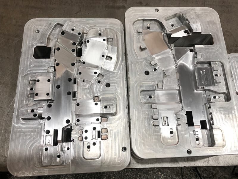
Aluminum
But do all molds need to be made of steel? Not necessarily.
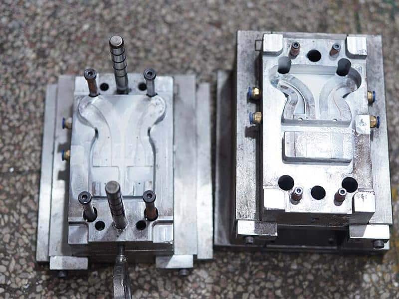
Aluminum molds are often used when speed and cost matter more than long-term durability. Because aluminum is easier to machine, mold lead time can be significantly reduced.
However, aluminum has lower wear resistance compared to steel, which limits its use to prototype molds or low-volume production runs. It is a practical choice when testing design concepts before committing to full-scale production.
Copper Alloys
In some cases, mold materials are not only chosen for strength, but also for thermal performance.
Copper alloys are rarely used as the main mold body, but they are sometimes applied in specific areas such as cooling inserts. This is because copper has excellent thermal conductivity, helping to speed up heat dissipation during the molding cycle.
By improving cooling efficiency, copper components can help reduce cycle time and improve part consistency in certain high-performance applications.
Key Factors That Affect Injection Mold Cost
Why do injection molds sometimes cost only a few thousand dollars, while in other cases the price can be many times higher?
The answer is that mold cost is not a fixed number, but the result of several design and manufacturing decisions. For example, how complex is the part itself? If the design includes undercuts, thin walls, or detailed features, the mold often needs additional mechanisms such as sliders or lifters. These elements make the tool more difficult to machine and assemble, which naturally increases cost.
Material choice also plays an important role. Different tool steels offer different levels of hardness, wear resistance, and processing difficulty. At the same time, molds designed for higher precision or tighter tolerances require more careful machining and inspection, which adds to both time and cost.
Finally, production expectations matter. A mold intended for long-term, high-volume production usually needs a stronger structure and more durable materials. Features like multi-cavity layouts or hot runner systems can also increase initial investment, even though they may reduce cost per part over time.
In short, mold cost is not just about the tool itself—it reflects the engineering behind it, and the balance between part design, material selection, and production goals.
Common Issues in Injection Mold Tooling and Troubleshooting
In injection molding, even well-designed tools can face production issues during mass manufacturing. Most of these problems are related to material flow, cooling behavior, or mold design details. Below are some of the most common defects and their general causes.
- Sink Marks – Usually caused by uneven wall thickness or insufficient cooling time, leading to localized shrinkage on the part surface.
- Warping – Often results from uneven cooling or internal stress, which causes the part to deform after ejection.
- Short Shot – Occurs when the mold cavity is not completely filled, typically due to low injection pressure, poor flow design, or insufficient material.
- Flash – Excess material leaking out of the mold parting line, usually caused by improper clamping force or worn mold surfaces.
- Weld Lines – Form when two flow fronts meet but do not fully fuse, often affecting both appearance and mechanical strength.
- Burn Marks – Caused by trapped air or excessive injection speed, leading to localized overheating inside the cavity.
If you want a deeper understanding of each issue and how to solve them in real production, you can explore our detailed guides on 20 Common Defects in Injection Molding.
Injection Mold Lifespan and Maintenance
How long can an injection mold actually last? The answer depends on several factors, including mold material, design quality, production conditions, and maintenance practices. Some molds may only be used for small batch production, while well-designed and properly maintained molds can run for hundreds of thousands or even millions of cycles.
Regular maintenance is essential to keep the mold in stable working condition. Without proper cleaning, inspection, and part replacement, even high-quality molds can experience wear, dimensional changes, or production instability over time.
If you want to understand this topic in more detail, including what affects mold life and how to improve it in real production, you can refer to our guide on Understanding and Improving Injection Mold Tool Life.
Other Types of Plastic Molding Tools
Although injection mold tooling is the most widely used method in plastic manufacturing, it is not the only solution. Different molding processes exist because products vary in shape, material behavior, and production needs.
So beyond injection molding, what other tooling methods are commonly used?
- Compression Molds – Often used for thermoset materials. Instead of injecting molten plastic, material is placed into the mold and shaped under heat and pressure until it solidifies.
- Blow Molds – Used when the product needs to be hollow, such as bottles or containers. Air pressure is used to expand molten plastic to match the mold cavity.
- Extrusion Dies – Designed for continuous shapes like pipes, sheets, or films, where material flows through a fixed profile rather than forming individual parts.
- Rotational Molding Tools – Used for large hollow products. The mold rotates while material coats the inner surface, gradually forming the final shape.
While the forming methods are different, they all follow the same idea: using a controlled tool to guide plastic materials into a defined shape that meets functional requirements.
Conclusion
Mold tooling is a key foundation of modern manufacturing, connecting product design with real-world production. Although the topic involves many technical aspects, understanding its basics—especially injection mold tooling—can help you better evaluate design decisions, production challenges, and overall manufacturing feasibility.
At Zhongde, we specialize in custom mold tooling design and plastic part manufacturing for a wide range of industrial applications. If you have a project in development or need technical support for mold design and production, feel free to contact our team to discuss your requirements.