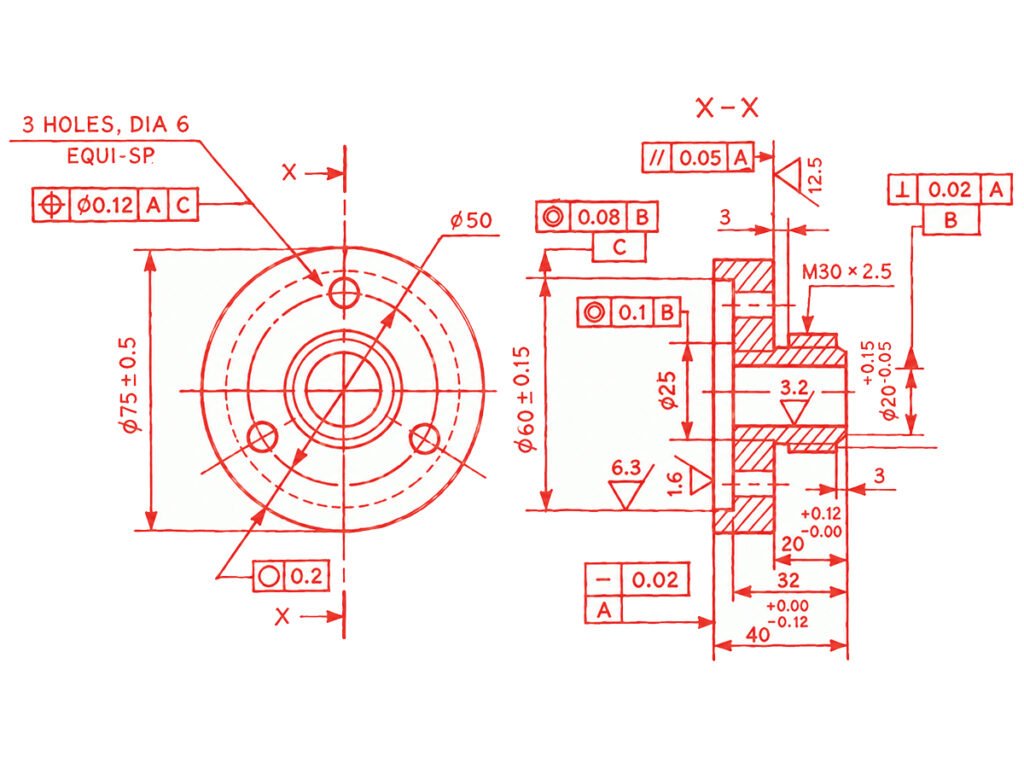
No part is ever made exactly to size. The question is how much variation the design can tolerate, and how to specify it clearly. This guide covers dimensional and geometric tolerances, and briefly explains what is often called surface tolerance, so you can read a print, question a quote, and negotiate with confidence.
What Does Tolerance Mean in Engineering?
In engineering, tolerance is the permissible variation in a physical characteristic of a part, most commonly its dimensions. No process reproduces a nominal value exactly, so a drawing specifies a nominal size with an allowable deviation. A shaft specified as 20 mm ±0.05 mm is acceptable anywhere between 19.95 mm and 20.05 mm, making 0.1 mm the tolerance zone.
Engineering tolerances cover more than size. Geometric tolerances control form, orientation, location, profile, and runout, while surface requirements address characteristics such as roughness. Each defines an allowable limit that a feature must stay within to remain functional and interchangeable.
Dimensional Tolerance
Dimensional tolerance defines the allowable variation in a size, whether a length, diameter, thickness, or angle. It is the most common type of tolerance on a drawing and a routine part of inspection, because it controls whether mating parts fit and function as intended.
Unilateral Tolerance
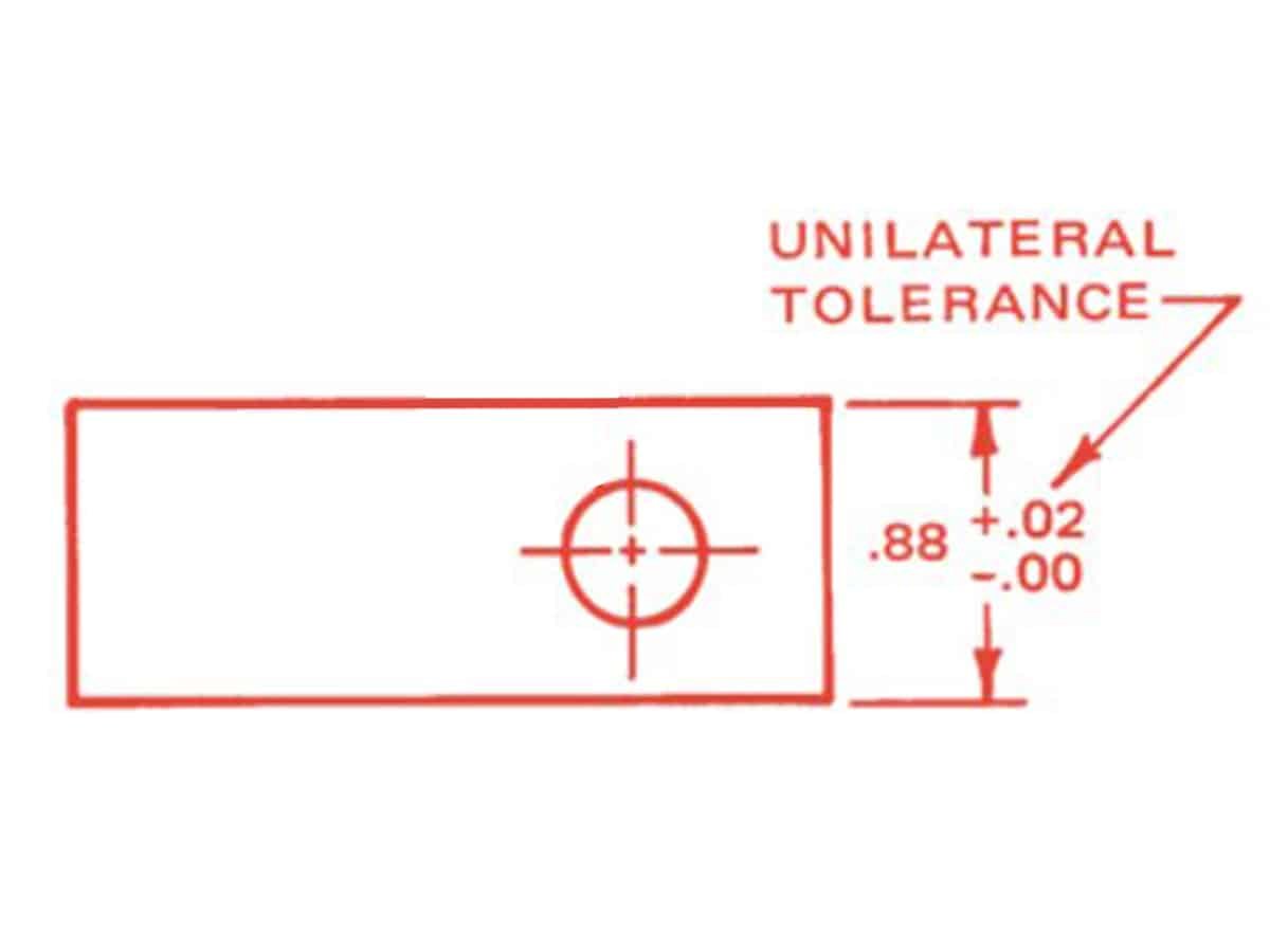
Unilateral tolerance allows deviation in one direction from the nominal size, with the other limit fixed. In the drawing above, the width is dimensioned as 0.88 in. +.02/−.00. The finished part may measure anywhere from 0.88 in. to 0.90 in.; anything below 0.88 in. is rejected.
This form suits features where one limit is critical, such as a bore that must not fall below a minimum diameter or a shaft that must not exceed a maximum. It is common in fits and shaft-hole assemblies because the nominal size can be set at the critical limit.
Machinists also favor unilateral tolerances when material is removed toward a known limit, because the part can be measured during machining and adjusted without crossing the critical boundary.
Bilateral Tolerance
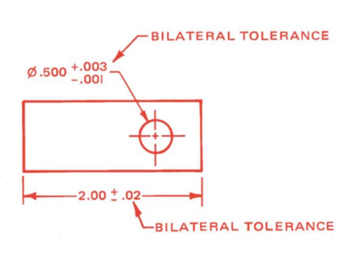
Bilateral tolerance allows deviation on both sides of the nominal size. In the drawing above, the overall length is dimensioned as 2.00 in. ±.02, so the finished part is acceptable anywhere from 1.98 in. to 2.02 in. When the plus and minus values are equal, as they are here, the tolerance is symmetric.
The two sides can also differ. The hole is dimensioned as Ø.500 +.003/−.001, giving a diameter range of 0.499 in. to 0.503 in. This unequal form suits cases where the process tends to vary toward one side or where function allows more variation in one direction.
Bilateral tolerance is common for general features because machining and molding processes can produce variation on either side of the target size.
Limit Tolerance
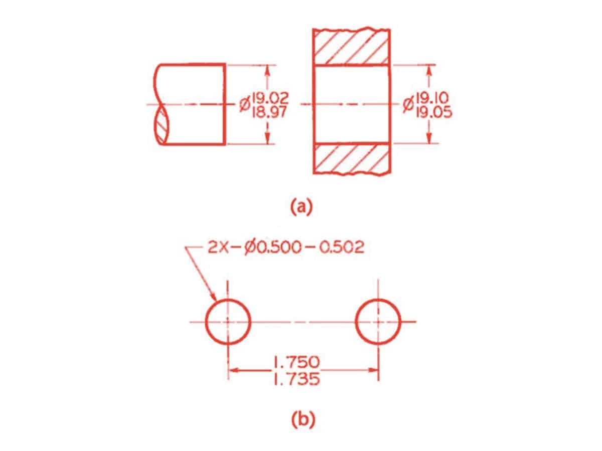
Limit tolerance states the two permitted extremes of a feature directly, with the upper limit on top and the lower limit below, so no calculation is needed. In the drawing above, the shaft in (a) is dimensioned as Ø19.02 / 18.97 mm, and the mating hole as Ø19.10 / 19.05 mm. The shaft may measure anywhere from 18.97 mm to 19.02 mm, and the hole from 19.05 mm to 19.10 mm.
The same format can appear on a single line, as in (b): the two holes are called out as Ø0.500–0.502 in., and the center distance as 1.750 / 1.735 in.
Limit tolerance is useful for mating parts because the upper and lower limits can be compared directly to check the fit.
General Tolerance
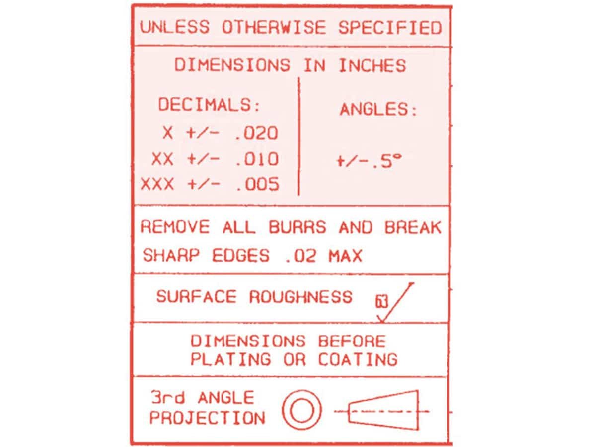
General tolerance applies to every dimension on a drawing that has no tolerance of its own. It is stated once, usually in the title block under “Unless otherwise specified.” In the drawing above, the tolerance depends on the number of decimal places: X ±.020 in., XX ±.010 in., and XXX ±.005 in., with angles held to ±.5°. A dimension written as 1.25 in. therefore allows ±.010 in., while 1.250 in. allows ±.005 in.
A drawing can also cite a standard instead of listing a table. ISO 2768 is widely used for machined parts, ISO 3302-1 for molded rubber products, and ISO 20457 for molded plastic parts. One note naming the standard and its class then applies to the whole drawing.
General tolerance keeps a drawing readable because only features that need tighter control require their own tolerance callout.
Geometric Tolerance
Size limits tell the machinist how large a feature may be. Geometric tolerance controls its form, orientation, location, profile, and runout, covering requirements such as straightness, flatness, roundness, squareness, and position.
Form Tolerance
Form tolerance controls the shape of a single feature. It needs no datum because the surface is checked against its ideal geometry. Four types are commonly used, and each defines a zone the actual feature must stay within.
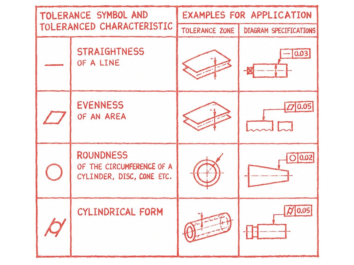
Straightness limits the deviation of a line element from a perfect straight line. In the figure, the shaft has a 0.03 in. callout, so every line along its surface must stay within a zone 0.03 in. wide.
Flatness (Evenness) limits the deviation of a surface from a perfect plane. A 0.05 in. callout places the entire surface between two parallel planes 0.05 in. apart.
Circularity (Roundness) limits the deviation of each cross-section from a perfect circle. The 0.02 in. callout on the tapered part keeps every section between two concentric circles 0.02 in. apart.
Cylindricity applies the same idea to the entire cylinder. A 0.05 in. callout keeps the surface between two coaxial cylinders 0.05 in. apart, controlling circularity, straightness, and taper in a single requirement.
Orientation Tolerance
Orientation tolerance controls the angle of a feature relative to a datum, so these controls use a datum reference. Three types cover the common cases: angularity, perpendicularity, and parallelism. Each one defines a zone between two parallel planes set at the required angle to the datum, and the controlled surface must stay inside it.
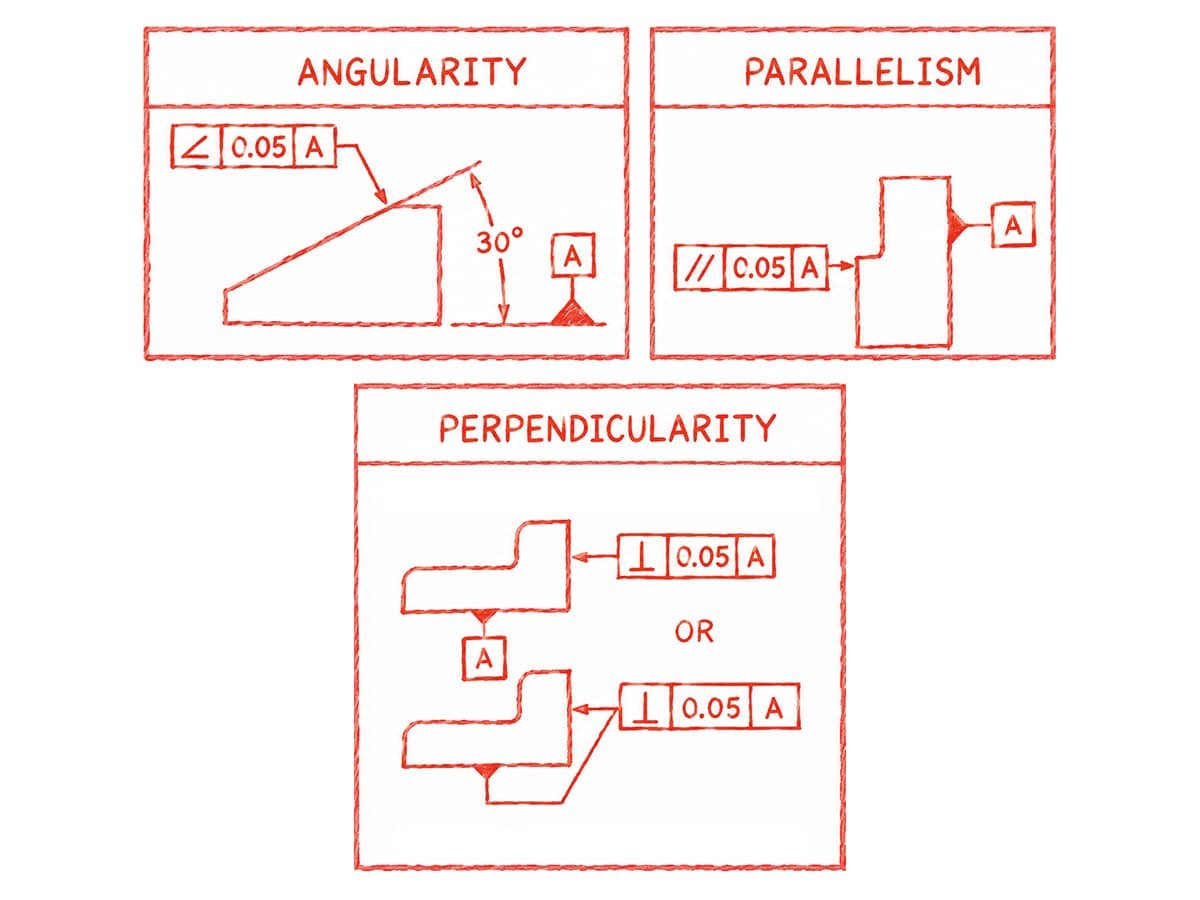
Angularity controls a surface that sits at an angle other than 90°. In the figure, the sloped face is called out at 30° to datum A with a 0.05 in. tolerance, so the face must lie between two parallel planes 0.05 in. apart, tilted at 30° to the datum.
Perpendicularity controls a surface that must sit at 90° to the datum. A 0.05 in. callout against datum A places the surface between two parallel planes 0.05 in. apart, both square to A. The figure shows the same callout written two ways.
Parallelism controls a surface that must run parallel to the datum, at an angle of 0°. With 0.05 in. against datum A, the surface lies between two planes 0.05 in. apart, both parallel to A.
Because the zone is a fixed pair of planes, an orientation tolerance on a surface also limits its flatness to the same value.
Location Tolerance
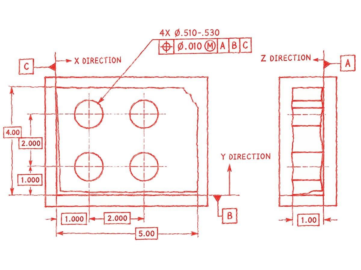
Location tolerance controls where a feature is located relative to the datums. Position is the most widely used type, and it is the one shown in the figure. The part is located from three datums: A for the Z direction, B for the Y direction, and C for the X direction.
The four holes are called out as 4X Ø.510–.530 in., and their centers are placed by boxed basic dimensions of 1.000 in. and 2.000 in. in both X and Y. The feature control frame sets a position tolerance of Ø0.010 in. at maximum material condition (MMC), referenced to A, B, and C. Each hole axis must stay inside a cylindrical zone 0.010 in. in diameter, centered on its true position.
The circled M adds a bonus: the zone grows as the hole moves away from its maximum material size. A hole at the .510 in. limit has a Ø0.010 in. zone, and a hole at the .530 in. limit has a Ø0.030 in. zone. This suits bolt patterns and other fastener holes, where a larger hole can accept more positional error.
Profile Tolerance
Profile tolerance controls the shape of a line or surface along an outline, making it a common control for curves, contours, and angled faces that no single size dimension can fully describe. It comes in two types: profile of a line, which applies to individual cross-sections, and profile of a surface, which applies to the whole surface.
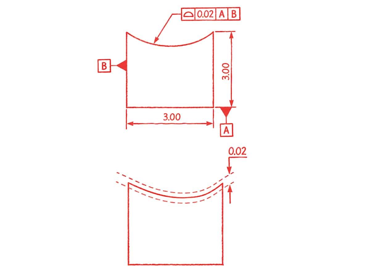
The figure shows profile of a surface on a 3.00 in. square part. The curved top face carries a 0.02 in. callout referenced to datums A and B. The tolerance zone is a band 0.02 in. wide between two dashed boundaries that follow the ideal curve, and the actual surface must lie inside it. Because datums are referenced, the callout also controls the location and orientation of the curve. Without datum references, the same callout would control its form alone.
Profile tolerance is common on molded and cast parts, where curved faces are common and one zone can control the entire contour.
Runout Tolerance
Runout tolerance controls how much a surface varies when the part turns 360° about a datum axis. Because the surface is measured against that axis, one callout limits variation caused by form errors such as out-of-roundness and errors in the surface’s position relative to the axis. Runout comes in two types: circular runout, shown with a single-arrow symbol, and total runout, shown with a double-arrow symbol.
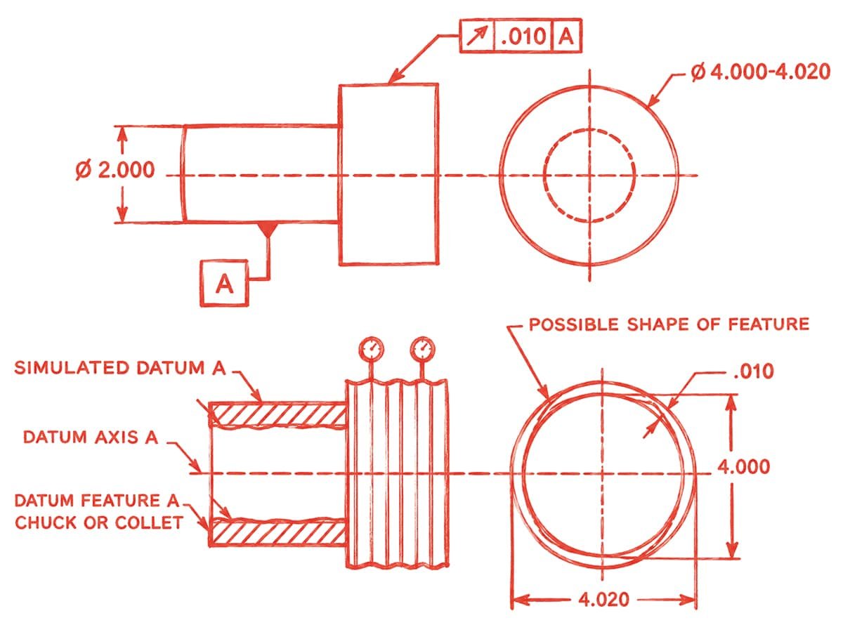
The figure shows circular runout. The Ø2.000 in. shank is datum feature A, held in a chuck or collet, and its axis becomes datum axis A. The Ø4.000–4.020 in. outer diameter carries a .010 in. callout referenced to A. A dial indicator rests on the surface while the part turns, and the full indicator movement at each cross-section must stay within .010 in. Each circular element is checked on its own, so the indicator can sit at a different position along the part for each check.
Total runout applies the same limit to the entire surface at once. The indicator travels along the length while the part turns, which also controls straightness and taper.
Surface Tolerance
Strictly speaking, surface texture is not a tolerance type. Dimensional and geometric tolerances define a size or zone that a feature must fall within. A surface callout sets a limit for a measured characteristic of the surface texture, most often roughness average (Ra), the arithmetic mean of the profile’s absolute deviations from its mean line. It has no nominal value or tolerance zone, and standards such as ISO 21920 and ASME Y14.36 treat it as a surface texture specification.
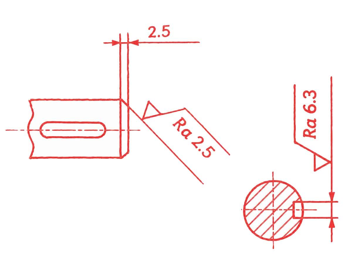
It still sits beside tolerances on the drawing and serves the same purpose of defining an acceptable part, so it is usually covered with them. In the figure, the shaft carries Ra 2.5 on its left view and Ra 6.3 on the keyway shown in the section at right. A lower Ra means a smoother surface, so the first is finished more finely than the second.
How Manufacturing Processes Affect Tolerance
Tolerance in manufacturing depends on the process used to make the part. Every process has its own natural level of variation, so the specified tolerance must match the process.
- CNC machining tolerances: Commonly holds tighter tolerances than most other processes, typically around ±0.005 in. and ±0.001 in. or better with careful process control. Tighter callouts add machining time and inspection cost.
- Plastic injection molding: Shrinkage, warpage, and wall thickness drive variation. Typical tolerances run about ±0.003 to ±0.010 in., depending on material and part size. See our guide to injection molding tolerances for material and feature specific considerations.
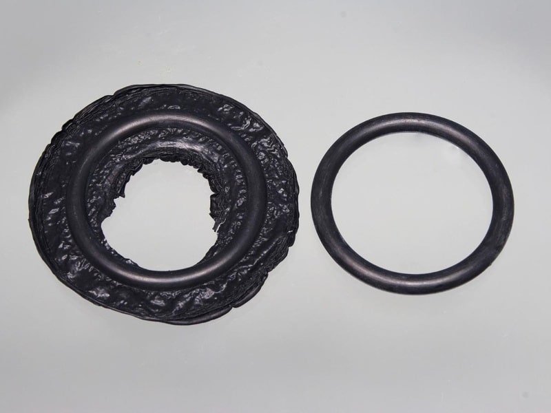
- Rubber molding (compression, transfer, injection): Rubber shrinks after cure and flexes under the measuring probe, so tolerances are usually wider than for plastic or metal. Standards such as ISO 3302-1 classify them by tolerance class.
- Die casting: Cooling shrinkage and die wear matter most. Small features commonly hold around ±0.005 in.
- 3D printing: Tolerance depends on the technology, and around ±0.010 in. is a common reference for plastic processes.
Conclusion
Clear tolerances make parts easier to quote, make, and inspect. Zhongde Custom Manufacturing Services can review your drawing with you and help balance tolerance requirements with your budget.