Injection molding is a common way of manufacturing high-quality, precisely crafted plastic parts. However, achieving precise and consistent tolerances can sometimes be challenging, especially when working with intricate geometries and stringent requirements.
Tolerances, defined as the permitted variance in dimensions, are essential to ensuring the final product’s performance and usefulness.
Today’s blog will be about injection molding tolerances and the four ways to improve them in this blog. By adhering to these recommendations, manufacturers can enhance process control, lower waste, and provide high-quality goods that satisfy customers.
Establishing Tolerance In Injection Molding
Determining tolerance is an essential step in the design and production processes of injection molding. Tolerance, the permitted range of departure from a stated dimension, is crucial for ensuring that the finished product fulfills the requirements. Consider the following factors while developing tolerance standards for injection molding:
Essential Injection Molding Tolerances To Specify Product Quality
Designers must consider various kinds of tolerance while manufacturing injection-molded parts. Here are the tolerance classifications, which are described in the injection molding tolerance guidelines, and include elements like:
- Dimensional tolerances
- Straightness/flatness
- Hole diameter
- Blind hole depth
- Coordinate/ovality
Each tolerance chart or table lists many tolerance substitutes for multiple materials and size ranges, some of which are more affordable and others more exact but more expensive. Designers must provide tolerances for essential features, like holes that need fasteners, besides dimensional tolerances. Designers also need to specify a generic tolerance and flatness callout instead, depending on the function of the part, such as for the foundation of a medical device.
Optimize Injection Molding Tolerance In 4 Ways
Achieving tolerance in injection molding is challenging because of many factors, including material qualities, mold design, and processing conditions. Tolerance is essential to ensure the final product’s performance and appearance. Manufacturers enhance consistency, dependability, and cost-effectiveness with these techniques:
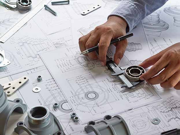
1. Design Parts For Manufacturability
It’s crucial to factor in moldability when designing. Our DFM (injection molding design for manufacturing evaluation examines some significant design advice meant to enhance the fabrication of your product, assuming there are any design flaws immediately. Use these design recommendations for your finalized injection-molded product to have exact dimensions.
Overall Size/Product Structure And Size
Injection molded parts commonly have a tolerance of 0.1 mm for spare applications, like certain consumer goods. 0.025 mm is used for applications that demand tighter tolerances, including injection-molded devices for medical use.
Designers must consider how each injection molded part will fit together while creating assemblies. This tolerance evaluation, also known as a tolerance stack-up, has to consider the required quantity of clearance along with any interference, including that caused by the fastener head.
Oversized injection molded items have higher shrinkage, making it more difficult to maintain their proportions. As a result, it is more challenging to maintain tighter tolerances for each component’s features and total part size.
Wall Thickness
A thick section will typically sink. Thick portions cool more slowly than thinner ones. As a result of the molten core shrinking inward and pulling the external walls alongside, it can cause divots and other flaws on the element’s exterior.
Parts with inconsistent wall thickness frequently warp, which implies they might not fall within the acceptable tolerance range. Uniform wall thickness across the entire component is the greatest approach to avoid these problems.
The below image shows the wall thickness design comparison.

Draft Angles
When considering manufacturing restrictions across the injection molding procedure, you must conform to design standards.
For example, ejection and milling from the mold both require a draft when molding. The part shape must be modified to efficiently mold a planned component with tolerances determined by models with an insufficient draft.
Draft angle modifications alter part dimensions, which in turn alter anticipated tolerances. Adding 1 to 2 degrees of the draft frequently functions effectively in most circumstances.
The below image shows the wall thickness design comparison.

Boss Features
- Rib Design: Boss features need to have a good rib design to increase stiffness and use less material. Between 60% and 80% of the structure’s width is expected to make up the rib thickness. Use this ratio to minimize sink marks and preserve a good-quality surface.

The above image shows the rib design comparison.
- Fillet Radius: The filter radius is crucial for boss features that prevent stress concentration at acute corners. A fillet radius of 0.5 – 1 times the structure’s thickness is recommended.
The bellow image shows the fillet radius design comparison.

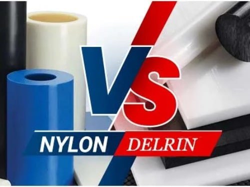
2. Choose The Right Material
The choice of resin is critical. Each substance has unique properties and cools down, runs smoothly, and solidifies into its final state at a variable rate. Finding the right material for the application could mean the differences between your part working and not working.
All substances contract when they cool in a mold. Consideration should be given to how the mold handles the component’s shrink rate, which is undoubtedly essential in the selection factor.
The below chart shows the common materials shrinkage rate chart for your reference.
To guarantee that you accomplish your desired tolerances, you must consider tool design, material selection, and part design together.
3. Remember Tool Considerations/Tool Design
Injection molding tolerance levels are heavily influenced by the tool design. The tool design must be precisely designed for the intended parameters to be met by the completed item. It is crucial to employ materials of excellent quality in the tooling to reduce the effects of damage caused by the use of the tooling.
Tooling Cooling System
A cooling system should be created to maintain a constant temperature throughout the tooling. The tooling must be properly cooled to reduce thermal stresses, affecting the preciseness of the injection molding processes.
The architectural layout of the mold frequently includes cooling channels that enable coolant to circulate through the tooling and maintain the same temperature throughout the process. The operating temperature of the tooling may be kept within a small range by making sure that the cooling infrastructure is optimized, leading to more precise and consistent molding.
Mold Accuracy
The mold’s tolerance is necessary to achieve the appropriate level of perfection in injection molding. The term “tolerance” describes the permitted deviations between dimensions, which must fall within a predetermined range for the part to operate properly.
Consider the mold’s tolerance throughout the design phase to ensure that the mold can produce the needed pieces with the necessary accuracy. Although a mold with tighter tolerances may produce a more exact component, the cost and complexity of the tooling may also rise.

Ejector Pin Location/Election Systems
The positioning of ejector pins and the ejection system affect the final product’s tolerance. After the item gets developed, the mold is removed using ejector pins. The position of the ejector pins should be carefully studied to prevent injuring the part during ejection.
The ejection mechanism should also be adjusted to deliver consistent and dependable part ejection from the mold. Improper ejection damages or distorts the part, which compromises its tolerance.
Gate Location
The tolerance of the finished product is affected by the gate’s location. The gate serves as where the molten plastic enters the cavity of the mold. The gate should be positioned so that proper material flow occurs and that it is free from potential flaws that affect the part’s tolerance. A gate that is positioned incorrectly results in sink marks, warping, or other flaws that reduce the precision of the item as a whole.
4. Process Controls For Quality Parts/Repeatable Process Controls
Scientific molding uses three aspects of the molding process—hold, fill, and pack. Whether it’s the first, the fifth, or the hundredth attempt, this procedure enables us to supply reliable parts. It’s an environmentally friendly procedure that guarantees the consistency of part dimensions from the start to completion and the reproducibility of every production process.
The functionality of what you sell depends more on specific attributes than others. For this reason, we advise you to highlight up to five CTQ (Critical-to-Quality) elements in your CAD framework, including tolerances. We pay even more attention to them as we work to satisfy your demands by highlighting the most necessary specifications. We can manufacture parts using CTQ that maintains consistency during manufacturing.
Injection Molding Tolerances Standard
A set of rules known as the “injection molding tolerances standard” establishes the permissible range of variation in the dimensions of plastic components made by injection molding. These tolerances are essential to ensuring that the finished product complies with the requirements and performs as planned. The design of the mold, the characteristics of the material being used, and the operating circumstances of the injection molding machine are just a few of the variables that impact injection molding tolerances.
Organizations like the Society of Plastics Engineers (SPE) and the International Organization for Standardization (ISO) set the criteria for injection molding tolerances. Adherence to these requirements is crucial for the consistency and quality of plastic parts produced by injection molding.