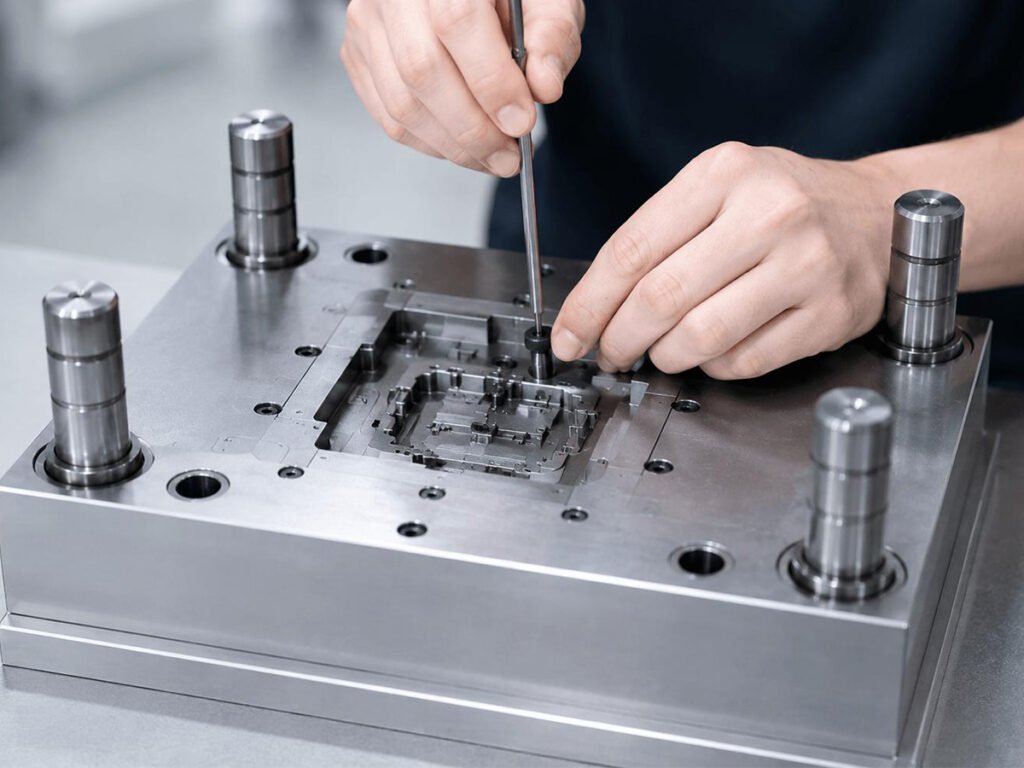
Mold assembly is a critical stage in mold manufacturing, involving not only the installation of mold components but also subsequent fitting, trial testing, and adjustments to ensure proper mold performance.
This article walks through the complete mold assembly process, explaining the key operations, techniques, and checkpoints at each stage. Along the way, we also clarify common terminology misunderstandings, such as confusing fitting with assembly or treating testing and adjustments as the same step, helping readers better understand how each stage contributes to a successful mold trial.
What Is Mold Assembly?
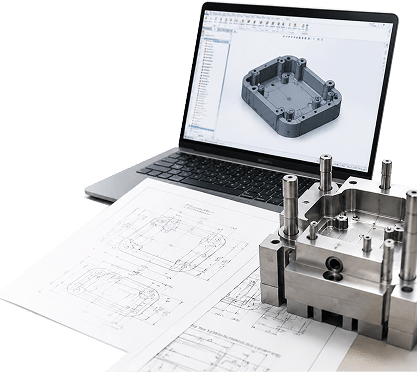
Mold assembly refers to the process of assembling individual mold components—such as cavities, cores, plates, guide pins, ejector systems, cooling components, and other mechanical parts—into a complete mold structure. It is a stage where precision machining and manual fitting work come together: every component must be positioned, aligned, and secured within specified tolerances so that the mold can operate reliably under the pressures and temperatures of the molding process.
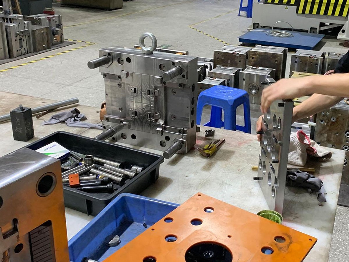
Fitting vs. Mold Trial vs. Adjustments: What’s the Difference?
- Fitting — The process of ensuring that individual mold components, such as cores, cavities, slides, and inserts, align and mate correctly with proper clearances and no interference. It usually takes place during and after assembly, before the mold enters production trials.
- Mold Trial (also called “T1 trial” or “trial testing”) — The process of running the assembled mold on an injection molding machine to produce sample parts and evaluate its performance under actual molding conditions, including filling, cooling, and ejection.
- Adjustments — Corrective actions taken after mold trials based on observed defects or performance issues. These may include modifying gates, improving vents, correcting parting surfaces, refining component fits, or adjusting molding parameters to achieve production-ready results.
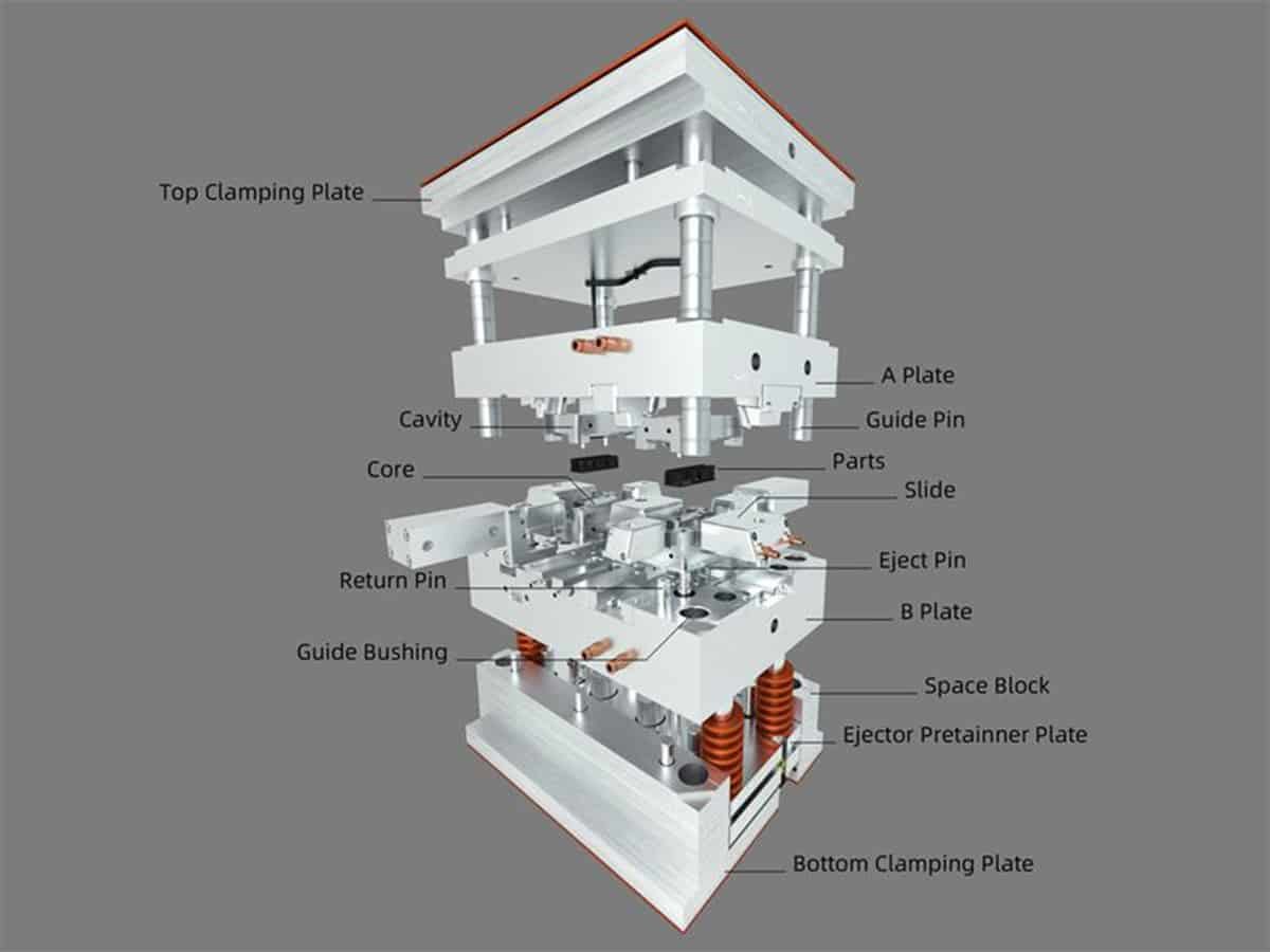
Mold Components Involved in the Assembly Process
Before starting the mold assembly process, it is important to understand the major components that must be assembled into a complete mold. Each component has a specific function, and proper assembly directly affects mold accuracy, durability, and production performance.
Mold Base
The structural frame that supports and secures all other mold components. It typically consists of clamping plates, support plates, guide components, and other structural elements that allow the mold to be mounted on an injection molding machine.
Core and Cavity
The core and cavity form the actual shape of the molded part. They are typically installed on the moving and fixed halves of the mold, respectively, and are usually among the most precision-machined components due to their direct impact on part geometry and surface quality.
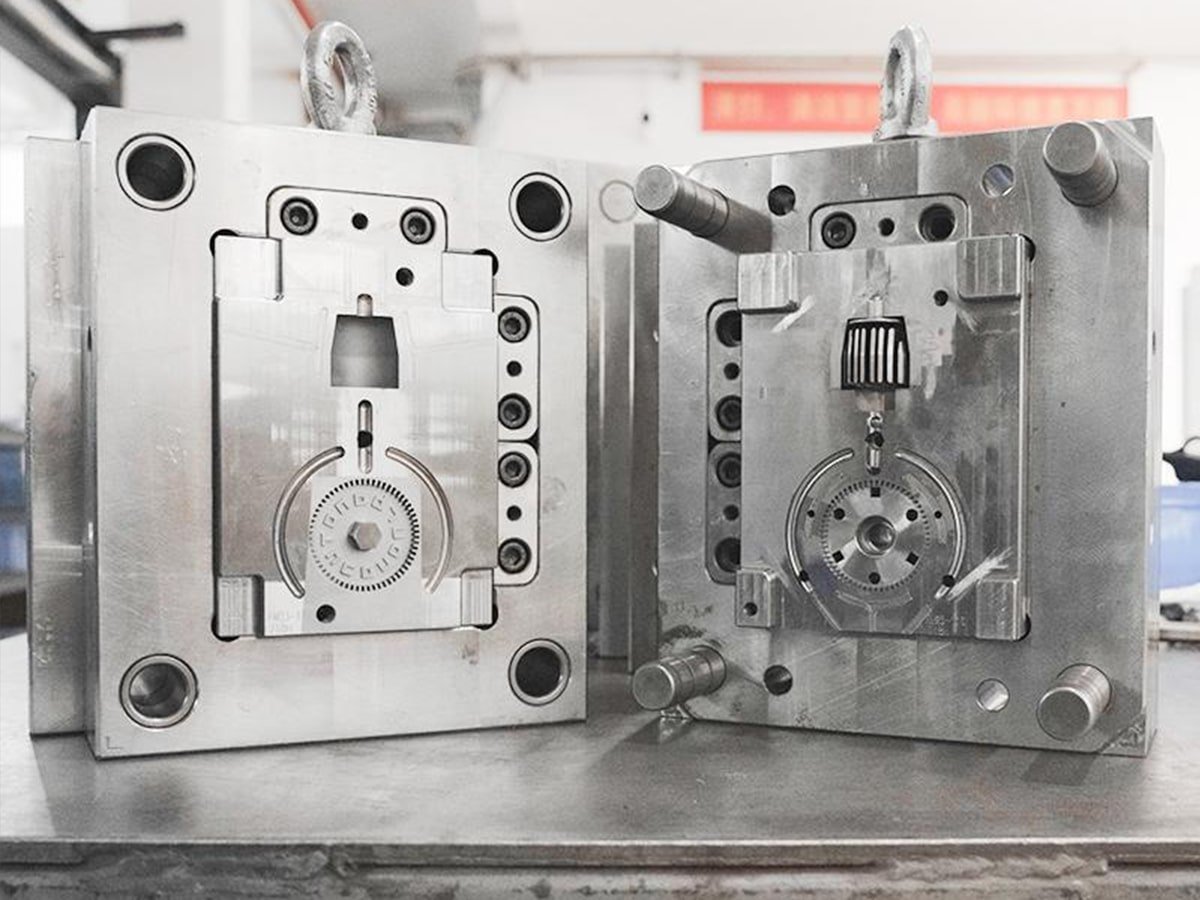
Guide Pins and Bushings
These alignment components ensure accurate positioning between the mold halves during opening and closing. During mold assembly, they help maintain proper alignment and reduce the risk of mismatch between core and cavity.
Ejector System
Consisting of ejector pins, ejector plates, and return pins, the ejector system removes the molded part after cooling and solidification. Proper assembly ensures smooth ejection without damaging the part surface or affecting cycle stability.
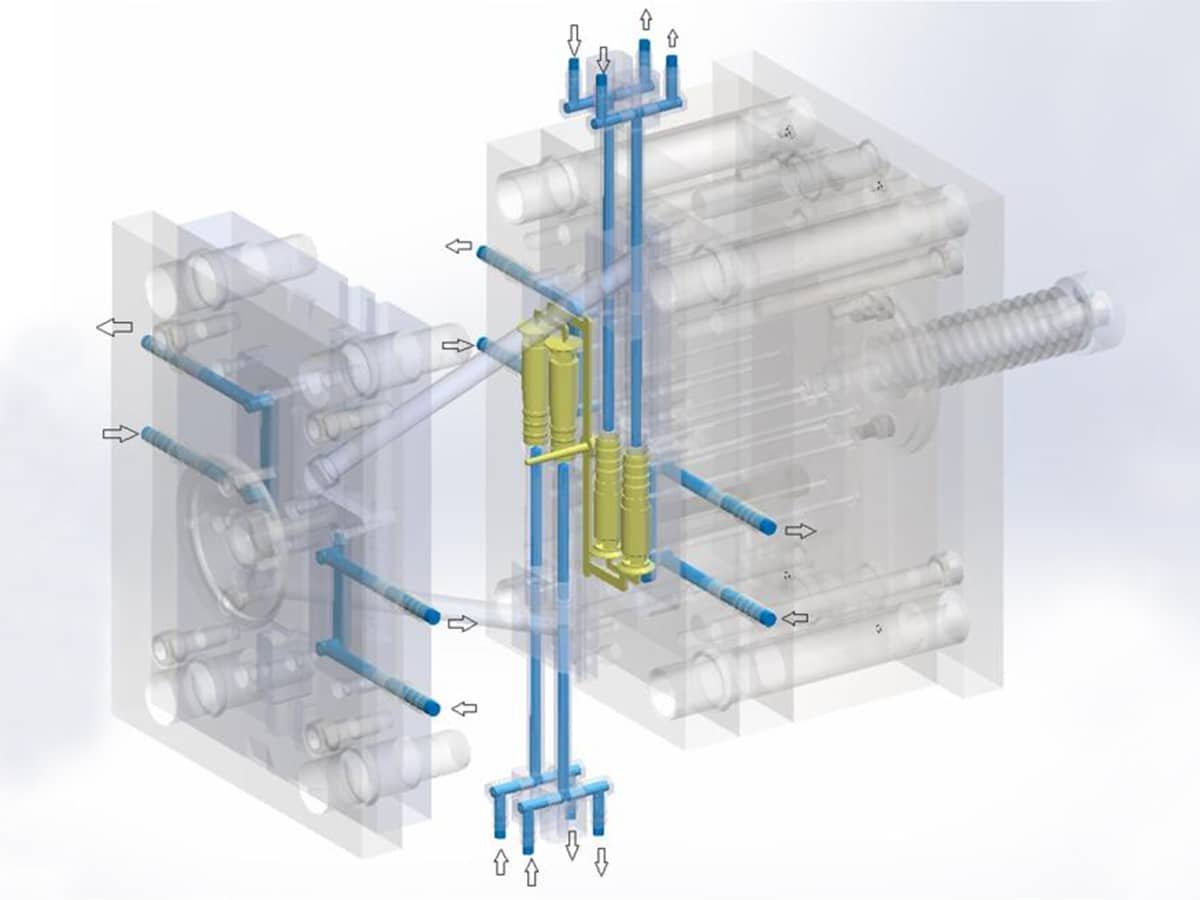
Cooling Channels
A network of channels machined into the mold plates that circulates coolant, usually water, to regulate mold temperature. Proper integration of cooling channels helps control cycle time and maintain consistent part quality.
Slides and Lifters
Used for molds with undercuts or complex features, slides and lifters are movable mechanisms that release areas that cannot be removed through a standard core and cavity separation.
Gating and Runner System
The material delivery system that guides molten plastic from the injection unit into the mold cavity. It includes the sprue, runners, and gates, and can be configured as a cold runner or hot runner system depending on production requirements.
Step 1: Assembly
With all components machined and inspected, the assembly stage begins—transforming individual parts into a working mold structure. This is a sequenced, precision-dependent process where the order of operations matters as much as the components themselves. Proper assembly ensures that each component fits together correctly and provides a stable foundation for later fitting, mold trials, and adjustments.
Sub-Plate Preparation
Assembly typically starts at the sub-assembly level rather than building the entire mold in one pass. Ejector systems are often assembled first—ejector pins, return pins, and sprue pullers (if used) are installed into their corresponding plate bores. Pin heights and movement are checked before the ejector plate and retainer plate are fastened together, ensuring smooth operation without interference during mold opening and closing.
Core and Cavity Insert Seating
Core and cavity inserts are installed into their designated pockets using controlled movement to prevent damage to precision surfaces. Fasteners are tightened in a cross-pattern sequence rather than around the perimeter in order, helping distribute clamping force evenly and prevent insert shifting or uneven seating. The key checkpoint at this stage is confirming that inserts sit flush with the surrounding plates and maintain the required alignment.
Guide Pin and Bushing Installation
Guide pins and bushings are installed to establish accurate alignment between the mold halves. Guide components typically use controlled fits: pins require secure positioning, while bushings require sufficient clearance for smooth engagement without excessive play. After installation, the alignment system should be checked by closing the mold halves manually to confirm smooth movement without binding or misalignment.
Cooling Line Integration
Cooling channels are connected using appropriate fittings, seals, or threaded adapters to prevent leakage during operation. O-rings or sealing materials are applied at connection points according to the mold design requirements. Cooling circuits are usually pressure-tested before the mold is fully closed, as open access makes leaks easier to locate and repair. Stable pressure retention confirms that the cooling system is ready for mold trials.
Sequential Plate Stacking
Mold plates are stacked in a defined order, typically including the ejector housing, support plates, cavity/core plates, and clamping plates. Locating components such as dowel pins are installed before final fastening to maintain plate positioning and prevent shifting during handling. After stacking, the assembly is checked for proper plate alignment and consistent fit between mating surfaces.
Torque Sequencing on Final Closure
When the mold is closed for the first time, clamping bolts are tightened in multiple stages rather than fully tightened in a single pass. A controlled sequence allows plates to seat evenly and reduces the risk of uneven stress or deformation. Final checkpoints include verifying bolt security, checking parting line contact, and confirming that moving components operate smoothly before proceeding to fitting and mold trials.
Step 2: Fitting
Once the mold is assembled, fitting verifies that individual components align correctly and function together as a complete system. Unlike assembly, which focuses on bringing components together, fitting focuses on refining contact surfaces, clearances, and movement accuracy before mold trials.
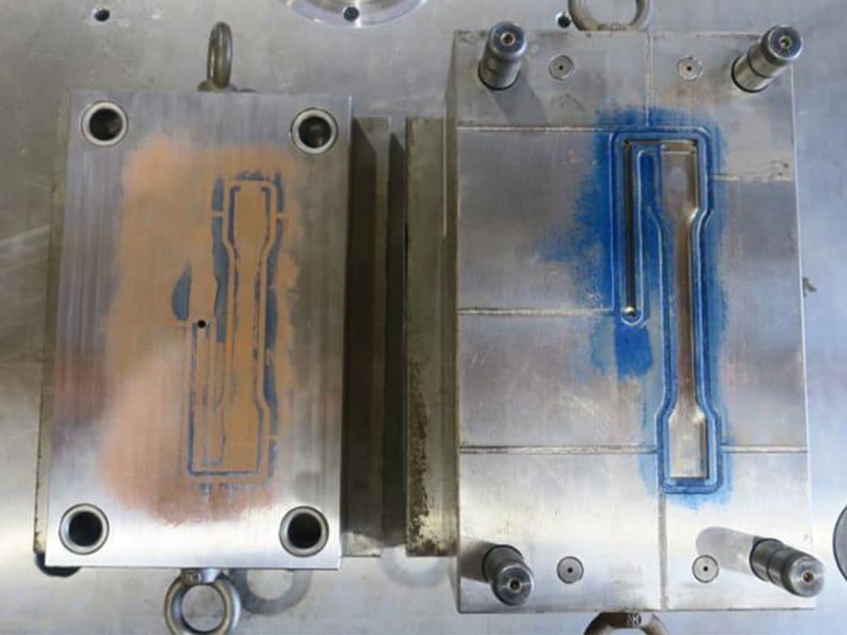
Parting Line Contact Check
Bluing (engineer’s blue) or a similar marking compound is applied to the parting surfaces, and the mold is closed under controlled pressure. The transferred pattern reveals uneven contact areas, which can be corrected through hand scraping, polishing, or surface adjustment until proper contact is achieved. This step helps prevent flash caused by poor parting line sealing.
Core-to-Cavity Shut-Off Verification
At shut-off areas where core and cavity surfaces meet, fitting confirms that contact is consistent and sufficient to seal the cavity. Engineers inspect witness marks, contact patterns, or measured clearances to identify gaps or excessive contact that could affect part quality during molding.
Slide and Lifter Motion Check
For molds with slides or lifters, fitting ensures smooth movement throughout the complete travel path. Components are checked for binding, improper timing, or interference with other mold features. Proper engagement between angle pins, cam mechanisms, and moving components is verified before trial operation.
Ejector Pin Alignment and Clearance
Ejector pins are checked for smooth movement within their bores and proper positioning when fully retracted. The goal is to ensure that pins do not stick, damage the mold surface, or leave unwanted marks on molded parts.
Dry-Cycle Movement Test
Before trial testing with plastic material, the assembled mold is cycled open and closed without injection. This dry run confirms that moving components—including slides, lifters, and ejector systems—operate in the correct sequence without abnormal resistance or interference.
Step 3: Trial Testing
With fitting confirmed, the mold moves to the injection molding machine for its first mold trial—commonly called a “T1 trial.” Unlike dry-cycle testing, this stage evaluates the mold under actual molding conditions using production material to verify filling behavior, part quality, and overall mold performance.
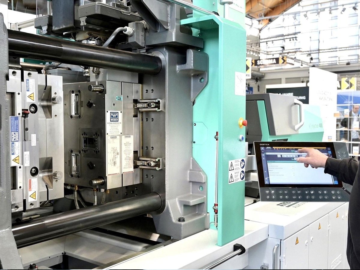
To learn more about mold testing, check out our previous article on Guide to Plastic Mold Test.
Press Setup and Mold Mounting
The mold is mounted on the injection molding machine, clamped securely, and aligned with the machine nozzle and platens. Cooling connections, hydraulic systems, and other auxiliary components are checked before operation. The machine is initially set with a conservative process profile to protect the mold while allowing engineers to observe its first molding behavior.
Short-Shot Progression
Instead of running a full shot immediately, the trial often begins with short shots at increasing fill levels. This allows engineers to observe material flow patterns, identify the last filling areas, and detect potential issues such as air traps or unbalanced filling before moving to full injection.
First Full-Shot Evaluation
Once the filling behavior is acceptable, a complete shot is produced and inspected. Key evaluation points include part dimensions, surface appearance, weld line location, ejection performance, and any defects such as short shots, sink marks, or flash.
Initial Process Adjustment
Based on the first trial results, molding parameters such as injection speed, pressure, holding time, and cooling time may be adjusted to improve part quality and mold performance. These adjustments help define a stable starting point for further optimization.
Repeatability Check
Multiple consecutive shots are produced under consistent settings to confirm that the mold performs reliably from cycle to cycle. Repeatability checks help identify issues that may not appear during a single successful shot and provide confidence before moving toward production preparation.
Step 4: Adjustments
Trial testing rarely produces a perfect result on the first attempt. Adjustments transform trial observations into corrective actions, addressing defects and performance issues before the mold moves toward production readiness.
Process Parameter Tuning
Based on trial results, injection speed, pressure, holding time, and cooling duration are refined to improve part quality and molding stability. These adjustments help resolve issues such as short shots, sink marks, warping, or inconsistent filling without modifying the mold structure itself.
Mold Modification
When process adjustments cannot fully solve the issue, physical changes are made to the mold. Common modifications include polishing surfaces to improve part release or appearance, adjusting gates to improve filling balance, improving vents to reduce trapped air, or correcting shut-off areas to eliminate flash.
Cooling and Ejection Refinement
If defects are related to uneven cooling, shrinkage, warping, or ejection marks, cooling performance and ejector movement may require further refinement. These changes ensure that the mold can produce parts consistently while maintaining smooth operation.
Verification Run
After adjustments are completed, another mold trial (such as T2 or T3) is performed to verify that the changes have resolved the original issues without creating new problems. This iterative process continues until the mold meets the required standards for production.
Troubleshooting Issues After Mold Assembly and Trial Testing
Even with careful assembly, fitting, and trial testing, molds may still develop issues during repeated production cycles. Some problems are not caused by initial assembly errors but appear only after thermal changes, mechanical wear, or long-term operation. The following section provides a practical reference for identifying common symptoms and their possible causes.
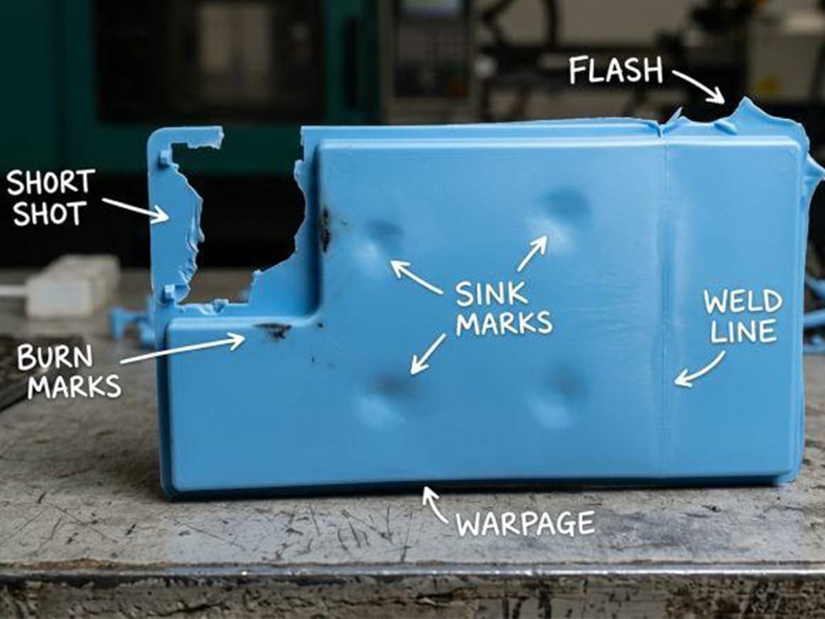
Flash at the Parting Line
Flash is often associated with poor fitting, but flash that appears only after extended production may indicate other issues, such as reduced clamping force, loose fasteners, worn support components, or thermal expansion differences between mold plates. Before re-fitting the parting surfaces, check clamp force, plate conditions, and mold temperature stability.
Inconsistent Part Weight Shot-to-Shot
Variation in part weight is not always caused by the mold. Issues with the injection unit, such as unstable melt control or a worn check ring, may allow material to flow backward during holding pressure. Confirm process repeatability first before making changes to the mold filling system.
Sticking Parts During Ejection
Parts that stick after molding may result from insufficient draft, surface finish problems, or vacuum effects in deep ribs and enclosed features. Possible solutions include improving venting, adjusting surface treatment, or refining the ejection method rather than immediately redesigning the ejector system.
Gradual Dimensional Drift During Production
When part dimensions gradually move outside tolerance after extended cycles, wear at guide components, insert seating areas, or shut-off surfaces may be responsible. This type of issue usually requires physical inspection and possible component repair or replacement rather than only adjusting molding parameters.
Intermittent Slide or Lifter Binding
Slides and lifters that operate correctly during trial but bind during production may be affected by thermal expansion, insufficient clearance, or lubrication issues. Inspection of wear surfaces, running clearances, and lubrication conditions can help restore stable movement.
Unexpected Weld Lines or Flow Marks
If weld lines or flow marks appear inconsistently between cycles, the cause may not be the mold design itself. Variations in material condition, moisture level, or molding parameters should be checked before modifying gates, runners, or vents.
Conclusion
Mold assembly is more than simply putting individual components together. It is a precision-driven process that ensures every mold component works correctly through fitting, trial testing, and final adjustments. Careful assembly and validation help prevent production issues, improve part consistency, and extend mold service life.
Choosing an experienced partner for the entire mold development process can reduce risks before production begins. Zhongde provides complete mold design and tooling service support, covering mold design, manufacturing, assembly, trial testing, and optimization to help turn your part designs into reliable production solutions.