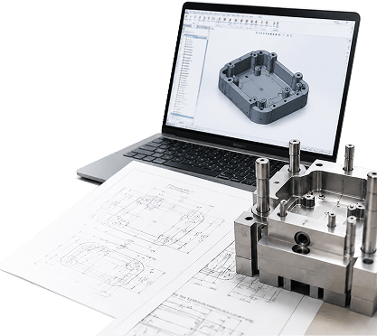
The guide system is one of the most overlooked components in injection mold design, yet it plays a critical role in controlling mold opening and closing movements and maintaining accurate alignment between the core and cavity throughout millions of production cycles. When it works properly, it often goes unnoticed. When it fails, the results can quickly become apparent: misaligned parts, uneven wear, and even damage to the mold itself.
This article explores how injection mold guide systems work, the key considerations behind effective design, and the details that help ensure reliable performance over the long term.
What Is an Injection Mold Guide System?
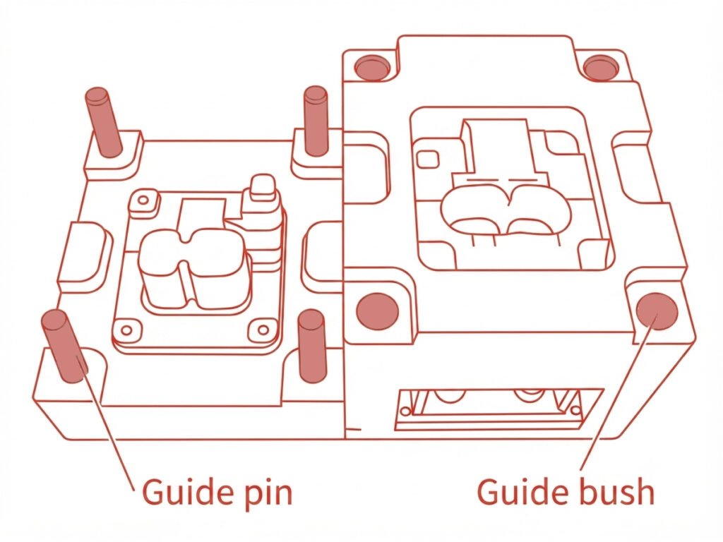
At its core, an injection mold guide system is the mechanism responsible for keeping the two halves of a mold—the moving half and the fixed half—properly aligned as they open and close during each molding cycle. It typically consists of guide pins (also called leader pins) and guide bushings, which work together to guide the mold halves into accurate alignment during closing.
In most designs, guide pins are mounted on one half of the mold and engage with corresponding bushings on the other half as the mold closes. This simple pairing, when properly sized, toleranced, and lubricated, allows a mold to run reliably for hundreds of thousands—or even millions—of cycles while maintaining alignment accuracy.
Guide System vs. Positioning System
It’s easy to confuse the guide system with the positioning system, but the two serve different purposes. The guide system—made up of guide pins and bushings—provides initial alignment of the mold halves during opening and closing, guiding them along a consistent path and helping resist lateral forces. It is designed for durability and repeated motion rather than final precision positioning.
The positioning system, on the other hand, takes over where precision really matters—typically around the cavity and core area. Components such as taper locks and interlocks ensure that the core and cavity achieve tight, repeatable alignment at the moment of mold closure, compensating for the small clearances inevitably built into the guide system. In short, the guide system brings the mold halves into alignment; the positioning system ensures precise alignment where it matters most.
Key Components of Injection Mold Guide System
A mold guidance system may include several components, but not all of them are required for every injection mold. Depending on the mold’s complexity, production volume, and precision requirements, some components are included in the initial design, while others are added to improve durability, accuracy, or ease of maintenance.
In most production injection molds, guide pins and guide bushings form the basic guide system, providing the foundation for maintaining alignment between the mold halves.
Guide Pins (Leader Pins)
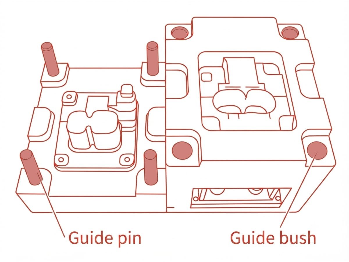
Guide pins are the backbone of the guide system—hardened steel pins typically mounted on the moving half of the mold. As the mold closes, they engage with corresponding bushings, guiding the two mold halves along a fixed and repeatable path. Their diameter, length, and hardness are selected based on factors such as mold size, weight, and operating conditions.
Guide Bushings
Paired with guide pins, guide bushings are precision-machined sleeves installed in the opposite mold half. They provide a wear-resistant surface for the guide pins to move through, reducing friction and helping minimize wear on the pins. Because bushings experience repeated contact during operation, they are often designed as replaceable components.
Optional Components of Injection Mold Guide System
Beyond the basic guide pins and bushings, more complex or high-volume molds may incorporate additional components to improve durability, precision, and maintenance efficiency.
Guide Plates
In molds with complex moving components, such as ejector plates, stripper plates, or sliding mechanisms, guide plates can provide additional support and guidance beyond standard guide pins and bushings. They help distribute lateral forces and keep moving components traveling along a controlled path. While not required for every mold, they become increasingly valuable as mold complexity increases.
Wear Plates
Wear plates are added to areas exposed to repeated sliding contact or friction. Acting as a sacrificial, replaceable layer, they protect more expensive mold components from gradual wear and help extend mold service life. They are especially common in high-volume production molds where long-term durability is critical.
Lubrication Components
Oil grooves, grease fittings, or self-lubricating bushings can be incorporated to keep the guide system operating smoothly. Although not required in every design, proper lubrication provisions are one of the most cost-effective ways to reduce wear and prevent premature guide system failure.
Design Guidelines of Injection Mold Guide System
Getting the guide system right isn’t just about selecting the right guide components from a catalog—it’s about how those components are positioned, sized, and integrated into the overall mold structure. A few key design principles can help prevent alignment issues and premature wear during long-term operation.
Pin Engagement Timing
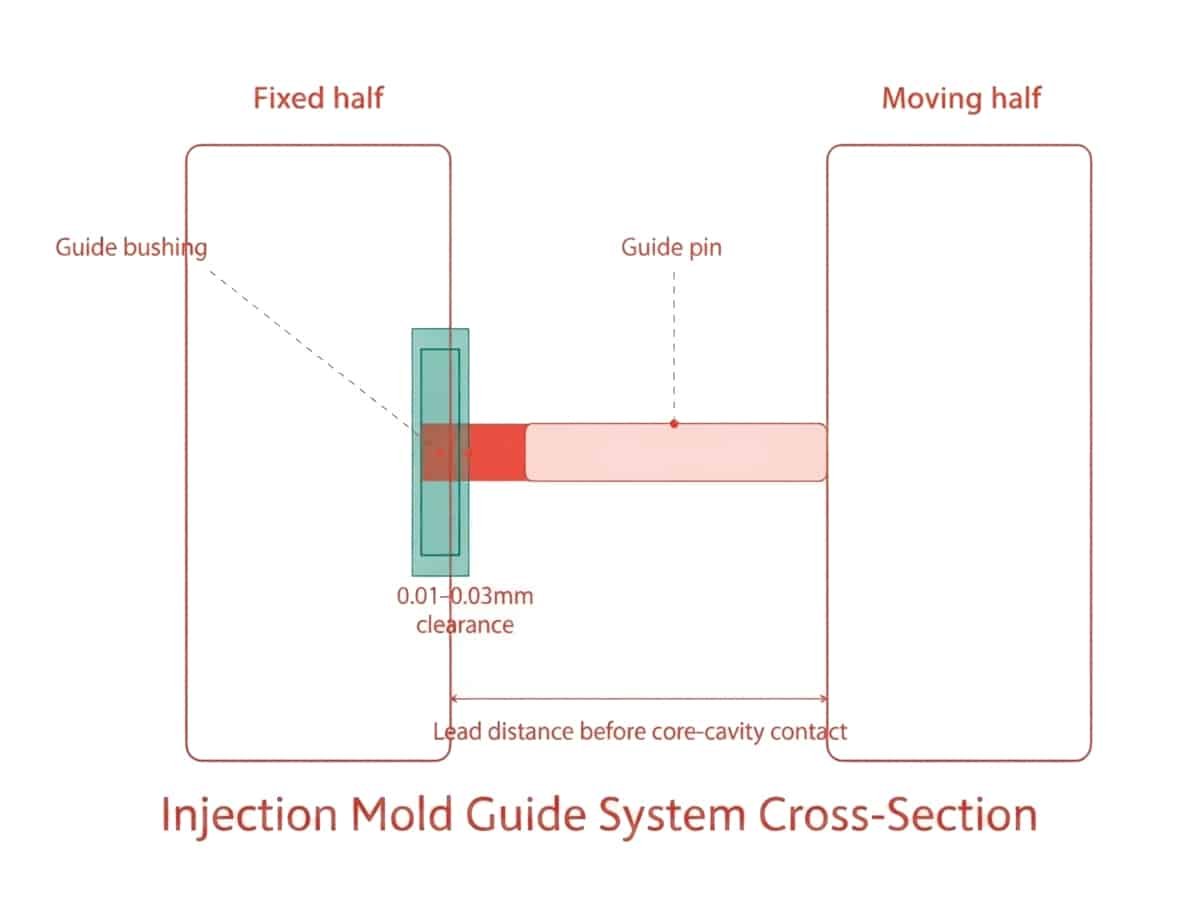
Guide pins should engage with their bushings before the core and cavity touch. This allows the mold halves to align before the precision mating surfaces come together. As a general guideline, pins often engage around 6–8 mm ahead of core-cavity contact, though larger or more complex molds may require a greater lead distance.
Pin and Bushing Sizing
Diameter and length should be selected based on the mold size, weight, and expected operating forces. Undersized pins may deflect or wear prematurely under lateral loads, while oversized pins add unnecessary bulk and cost. As a general reference, many designers start with guide pin diameters around 1/8 to 1/10 of the mold plate’s smaller dimension, then adjust based on clamping tonnage, mold weight, and accuracy requirements.
Symmetrical Placement
Guide pins should be arranged to prevent incorrect mold closure—often using an asymmetrical layout, such as one offset or oversized pin, so the two mold halves can only align in one correct orientation. This simple design feature helps prevent assembly errors and potential mold damage.
Fit and Clearance
The clearance between guide pins and bushings requires careful balance: too tight, and the assembly may bind or experience galling due to thermal expansion; too loose, and alignment accuracy can suffer. A typical clearance for precision molds is around 0.01–0.03 mm, although the actual value depends on mold size, operating temperature, and required tolerance.
Material and Hardness Selection
Guide pins and bushings are typically hardened to different levels, with the pin often slightly harder than the bushing. This helps concentrate wear on the more easily replaceable component rather than the guide pin, extending service life and reducing maintenance frequency.
Conclusion
Understanding how a mold guide system works can help you make better design decisions, reduce alignment issues, and extend mold service life. At Zhongde, we focus on precision mold design and reliable injection molding solutions tailored to your part requirements. Contact us to discuss your project.