Plastic injection molding can produce dozens of defects, but these 10 are among the most representative, covering distinct problems related to plastic materials, mold design, process parameters, and processing conditions. Understanding their causes and corrective measures provides a practical framework for troubleshooting plastic injection molded parts.
Warpage
Warpage is the distortion or bending of a plastic molded part away from its intended flat or designed shape, causing it to twist, bow, or curl after ejection and cooling. It can become more pronounced hours after molding as internal stresses continue to relax.
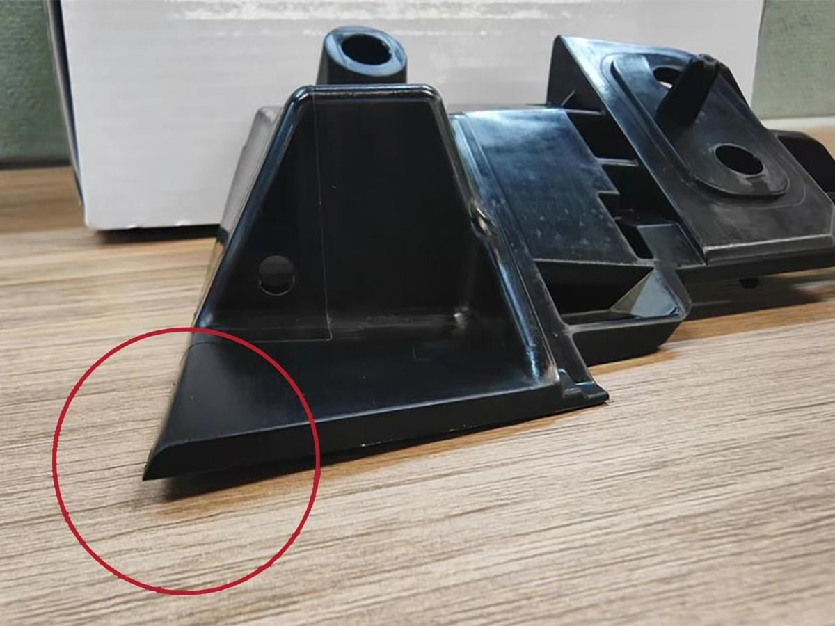
Common locations: Thin, flat panels; long unsupported walls; parts with uneven wall thickness; areas near gates or ribs where cooling differs from the rest of the part.
Causes:
- Uneven cooling rates across the mold or part
- Inconsistent wall thickness causing differential shrinkage
- Excessive or unbalanced packing pressure
- Poor gate placement causing uneven material flow
- Ejecting the part before it is sufficiently cooled
- Molecular or fiber orientation differences in the material
Prevention:
- Design uniform wall thickness wherever possible
- Balance cooling channels for even mold temperature
- Optimize gate location and number for balanced flow
- Adjust packing pressure and holding time appropriately
- Allow adequate cooling time before ejection
- Use ribs or structural features to add rigidity without adding mass
Sink Marks
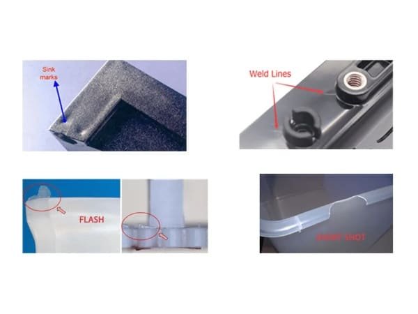
Sink marks are small depressions or dimples that appear on the surface of a molded part, typically above thicker sections. They occur when the outer skin solidifies while the thicker interior is still cooling and shrinking, pulling the surface inward.
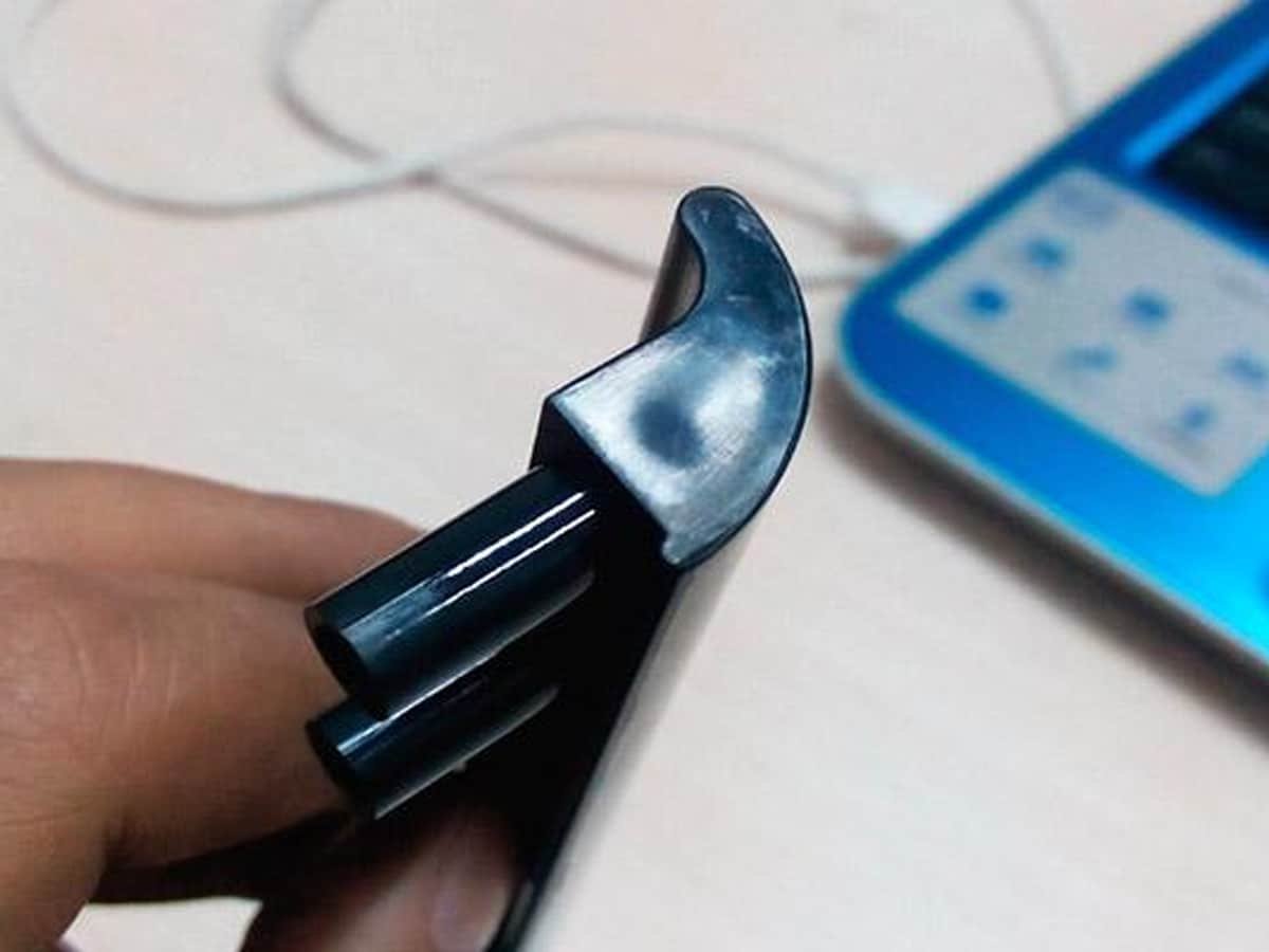
Common locations: Behind ribs, bosses, and thick walls; at gate areas with heavy sections; near thickness transitions.
Causes:
- Wall sections that are too thick relative to surrounding areas
- Insufficient packing pressure or packing time
- Gate freezing off too early, cutting off material feed
- Low melt or mold temperature causing uneven cooling
- Ribs or bosses too thick relative to the nominal wall
Prevention:
- Keep rib/boss thickness to 50–60% of the adjoining wall
- Increase packing pressure and holding time
- Delay gate freeze-off or enlarge the gate size
- Optimize melt and mold temperatures for uniform cooling
- Position gates closer to thick sections
- Use coring or ribbing to reduce effective wall thickness
Short Shots
A short shot occurs when molten plastic fails to completely fill the mold cavity, resulting in an incomplete part or missing sections. The part may show clean, rounded edges where the flow front stopped before reaching the end of the cavity.
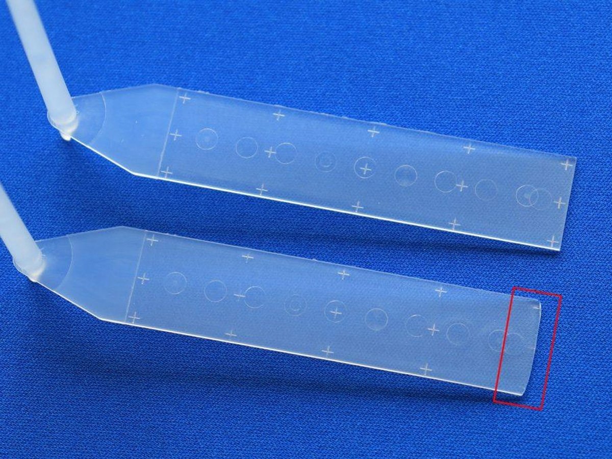
Common locations: Areas farthest from the gate; thin walls or narrow flow paths; extremities such as corners, ribs, and fine details.
Causes:
- Insufficient injection pressure or speed
- Melt temperature too low, causing premature solidification
- Inadequate shot size or material supply
- Poor venting, trapping air that restricts flow
- Undersized gates, runners, or flow channels
- Excessive flow length relative to wall thickness
Prevention:
- Increase injection pressure, speed, or shot size as needed
- Raise melt or mold temperature to maintain flowability
- Improve venting to allow trapped air to escape
- Enlarge gates and runners for easier material flow
- Optimize wall thickness to avoid overly long, thin flow paths
- Verify sufficient plasticizing capacity for the part volume
Flash
Flash is a thin, unwanted layer or fin of excess plastic that forms along the parting line, around ejector pins, or at vents. It appears as a protruding edge where material escapes the cavity through small gaps in the mold.
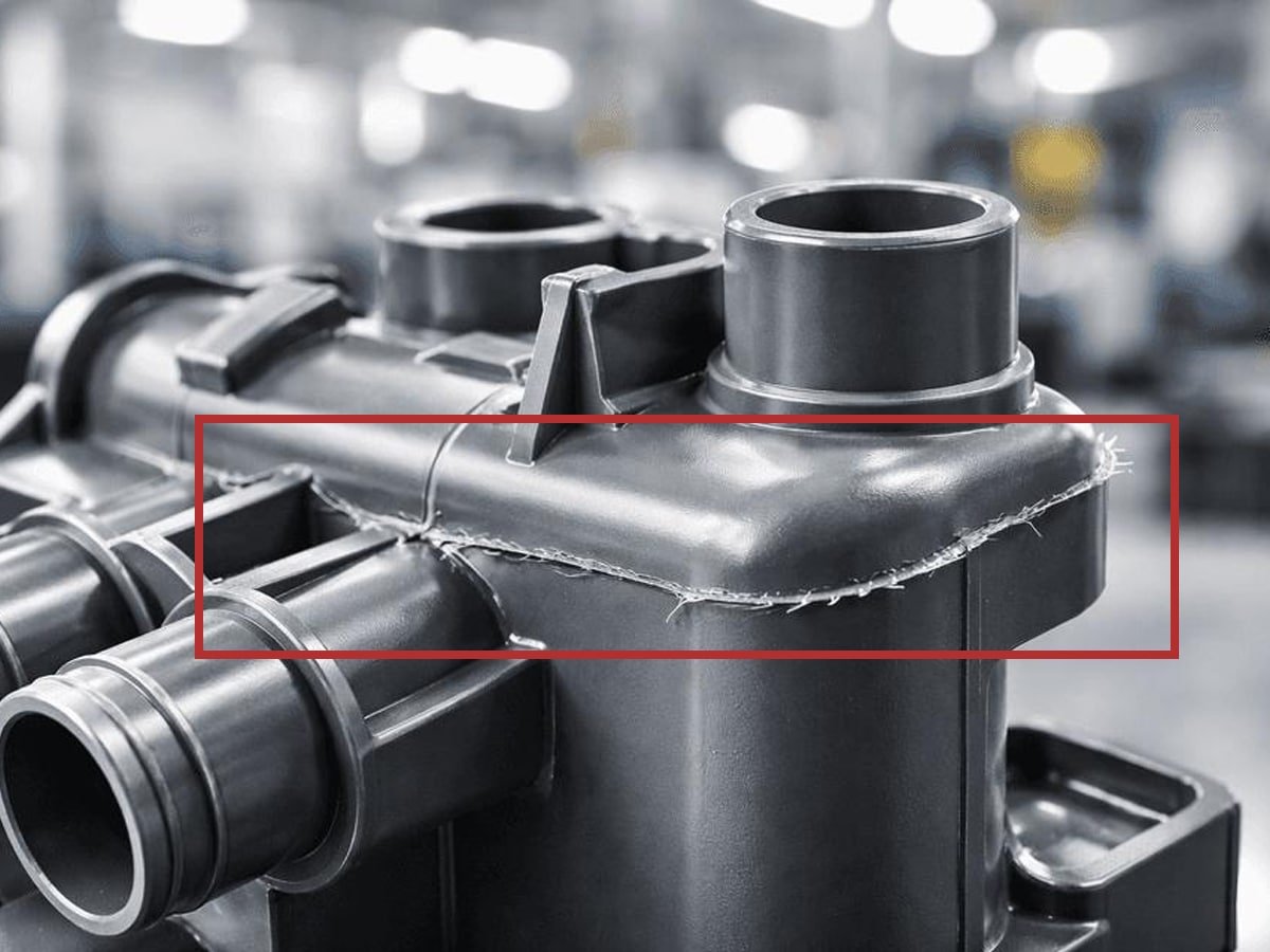
Common locations: Parting lines; ejector pin holes; vents; mold slides and inserts where mating surfaces meet.
Causes:
- Excessive injection pressure or speed
- Insufficient clamping force to keep the mold fully closed
- Worn, damaged, or poorly fitted mold components
- Mold not properly aligned or fully closed
- Melt temperature too high, reducing melt viscosity
- Cavity contamination preventing a tight seal
Prevention:
- Balance injection pressure and speed to the part’s needs
- Ensure clamping force matches the projected part area
- Inspect and maintain mold surfaces, vents, and parting lines
- Verify proper mold alignment and closure before production
- Keep melt temperature within the recommended processing range
- Perform regular mold cleaning and maintenance
Weld Lines
Weld lines (also called knit lines) are visible seams or faint lines that form where two or more flow fronts of molten plastic meet and fuse during filling. Because the fronts may have partially cooled before merging, the resulting bond can be weaker and cosmetically visible.
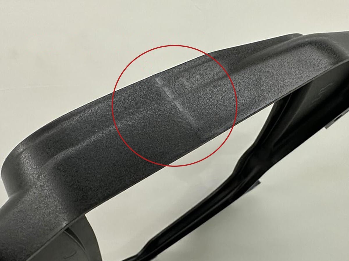
Common locations: Around holes, inserts, or obstructions; areas where flow splits and rejoins; parts with multiple gates.
Causes:
- Low melt or mold temperature causing premature cooling of flow fronts
- Slow injection speed allowing fronts to cool before meeting
- Poor gate placement forcing flow to split unnecessarily
- Insufficient venting at the meeting point
- Large flow-length differences between converging fronts
- Incompatible or contaminated material reducing fusion quality
Prevention:
- Increase melt and mold temperature to improve fusion
- Raise injection speed to keep flow fronts hotter longer
- Optimize gate location/number to minimize or reposition weld lines
- Improve venting at likely weld-line locations
- Balance flow paths so fronts meet with similar temperatures
- Consider design changes to move weld lines to non-critical areas
Flow Marks
Flow marks (or flow lines) are wavy, ripple-like patterns or streaks visible on the part’s surface, often appearing as bands or rings near the gate. They trace the path of the melt front as it advanced unevenly through the cavity.
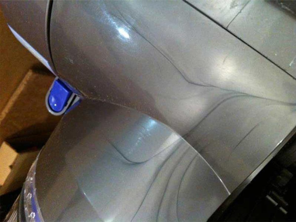
Common locations: Near the gate; along thin sections; areas with abrupt changes in flow direction or wall thickness.
Causes:
- Melt or mold temperature too low, causing the flow front to cool unevenly
- Injection speed too slow, allowing partial solidification during filling
- Gate too small or poorly positioned, disrupting smooth flow
- Excessive viscosity or poor material flowability
- Abrupt wall thickness changes disturbing the flow front
Prevention:
- Increase melt and mold temperature for smoother flow
- Raise injection speed to maintain a consistent flow front
- Enlarge or reposition the gate for more even filling
- Select material grades with suitable flow characteristics
- Design smoother transitions between wall thicknesses
- Optimize the runner and gate system for balanced flow
Burn Marks
Burn marks are dark, brown, or black discolored spots—sometimes accompanied by a scorched smell or surface degradation—caused by overheated or degraded plastic. They can also appear as charred patches when trapped air is rapidly compressed, generating enough heat to degrade the surrounding material.
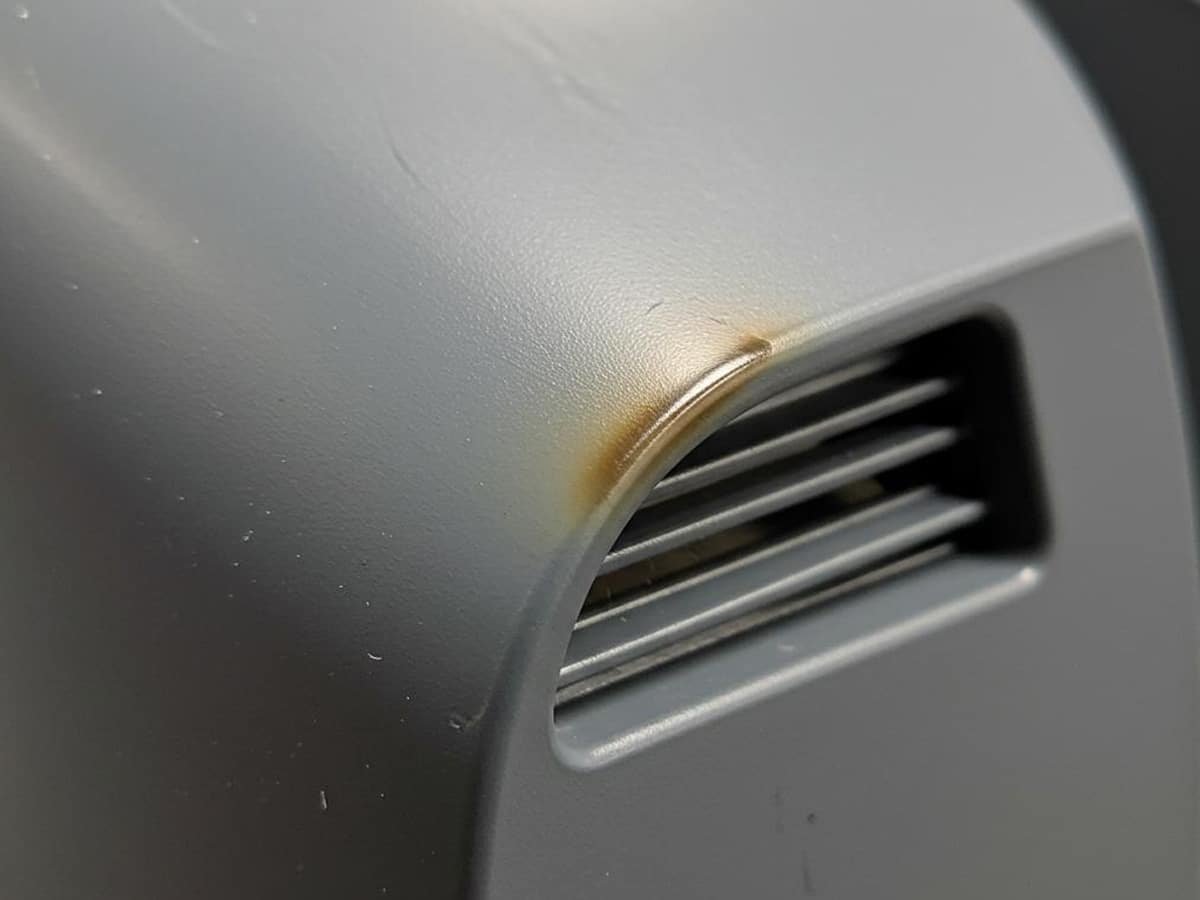
Common locations: Weld line areas; poorly vented pockets; ends of flow paths; deep ribs or thin, restrictive sections.
Causes:
- Trapped air compressed rapidly, generating heat (dieseling effect)
- Melt temperature too high, degrading the material
- Excessive injection speed causing shear heating
- Inadequate venting preventing air from escaping
- Material residing too long in the barrel, causing thermal degradation
- Contaminated or improperly dried resin
Prevention:
- Improve mold venting at trapped-air-prone locations
- Reduce melt temperature and injection speed as appropriate
- Adjust barrel temperature profile and reduce residence time
- Ensure proper material drying and handling before molding
- Add or enlarge vents along the flow path and at weld areas
- Regularly clean and inspect the mold for vent blockages
Silver Streaks
Silver streaks are thin, silvery, splay-like streaks or hairline patterns that appear on the part’s surface, usually running in the direction of material flow. They’re often caused by moisture or gas escaping from the melt and leaving streaks as the material flows through the cavity.
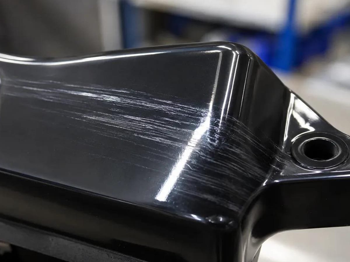
Common locations: Near the gate; along flow paths; surfaces of parts made from hygroscopic materials.
Causes:
- Moisture in the resin vaporizing during injection
- Material overheating and degrading, releasing gas
- Excessive shear from high injection speed or small gates
- Contaminated or mixed regrind material
- Trapped air entrained into the melt during plasticizing
- Barrel or nozzle temperature set too high
Prevention:
- Properly dry resin according to manufacturer specifications
- Lower melt and barrel temperatures to prevent degradation
- Reduce injection speed and shear at the gate
- Use clean, uncontaminated material and controlled regrind ratios
- Check screw design and back pressure to minimize air entrapment
- Enlarge gates to reduce shear during filling
Voids
Voids are small, hollow cavities or bubbles trapped inside a molded part, invisible from the outside but often detectable by X-ray, cross-section, or a hollow sound when tapped. They form when the interior of a thick section shrinks faster than the surrounding material can compensate.
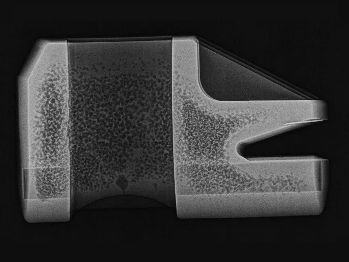
Common locations: Thick sections; ribs and bosses; areas farthest from the gate; centers of heavy cross-sections.
Causes:
- Insufficient packing pressure or packing time
- Uneven cooling causing the outer skin to solidify before the core
- Wall sections too thick, leading to uneven shrinkage
- Gate freezing off too early, cutting off material feed
- Low injection pressure failing to fully pack the cavity
- Trapped air not escaping during filling
Prevention:
- Increase packing pressure and extend holding time
- Design uniform wall thickness to reduce shrinkage differences
- Enlarge gates or adjust gate location for better packing
- Optimize cooling to balance skin and core solidification
- Improve venting to release trapped air
- Reduce wall thickness or add coring in heavy sections
Color Unevenness
Color unevenness (also called color streaking or mottling) refers to inconsistent, patchy, or streaky coloration across a molded part’s surface, where color appears lighter, darker, or unevenly distributed rather than uniform. It can range from subtle shading differences to distinct streaks or swirls.
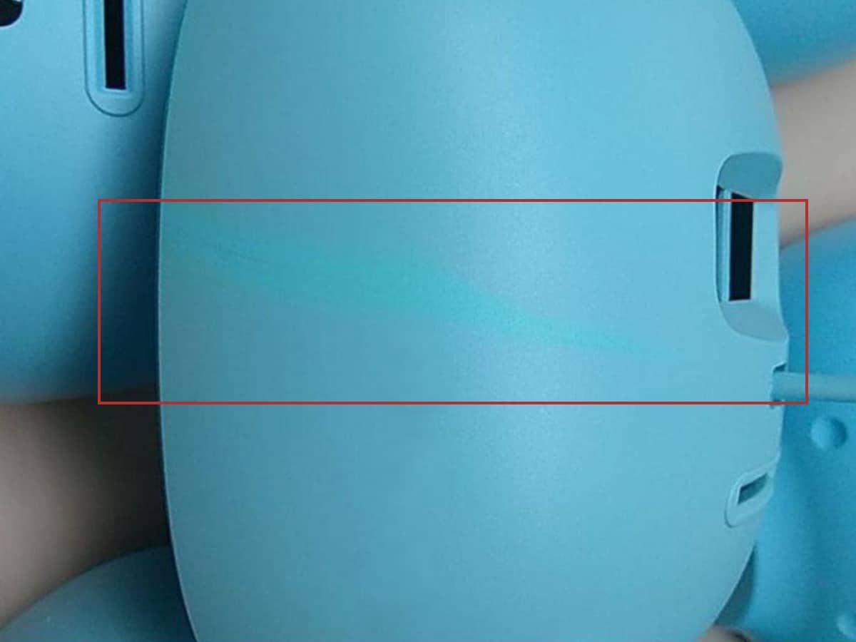
Common locations: Near the gate; along weld lines; areas with abrupt flow direction changes; surfaces exposed to varying cooling rates.
Causes:
- Poor mixing of colorant/masterbatch with base resin
- Inconsistent melt or mold temperature affecting color consistency
- Excessive shear or residence time degrading colorant
- Incompatible or unsuitable colorant for the resin type
- Uneven cooling rates causing differential gloss or crystallinity
- Contamination from regrind or mixed material batches
Prevention:
- Ensure thorough, consistent colorant/resin mixing before molding
- Maintain stable melt and mold temperatures throughout the cycle
- Use colorants compatible with the specific resin and process
- Minimize shear and residence time to prevent colorant degradation
- Control regrind ratio and material consistency
- Optimize screw design for better melt homogenization
For a broader look at injection molding defects beyond the 10 covered here, see our Injection Molding Defects guide.
Conclusion
While these 10 defects are among the most representative of plastic injection molding, their causes—and even their appearances—can overlap, since the process involves many interdependent variables. Our plastic injection molding team can help identify the causes, refine mold and process conditions, and maintain consistent part quality. Learn more about our plastic injection molding services.