Voids in injection molding are a common injection molding defect. Various reasons cause it. Voids can vary in size and location, sometimes being visible on the part’s surface or hidden internally, potentially compromising the part’s structural integrity and functionality. In this post, Zhongde custom plastic manufacturing will explore the causes of injection molding voids and the prevention strategies.
What are Voids in Injection Molding?
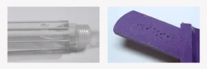
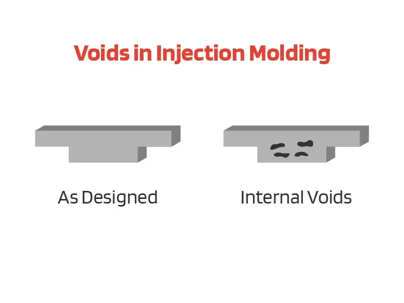
Voids in injection molding are cavities or spaces that form within the thicker sections of an injection-molded product during the cooling process. These voids in plastic parts are essentially areas where the plastic material did not fill the mold. They occur when the outer layer of the part cools and solidifies faster than the interior, causing the inner material to shrink and create a space. They typically appear as “air pockets” in transparent parts but can also be present in colored or opaque moldings.
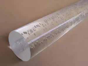
In transparent parts, injection molding voids are easily visible as “air pockets” within the plastic. In opaque or colored parts, voids are not readily visible from the outside. They can only be discovered by sectioning the part or using advanced detection methods like CT scanning.

Types of Voids in Injection Molding
Two main types of voids in plastic parts can occur in injection molding:
Vacuum voids:
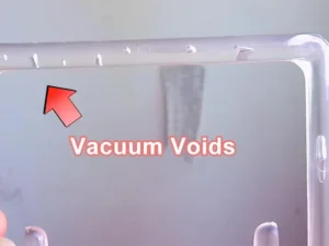
Vacuum voids are the most common type of void in injection molding. They form when the outer layer of the part cools and solidifies faster than the interior, causing the inner material to shrink and create a space. Vacuum voids typically occur in thicker sections of the molded part. They appear as “air pockets” in transparent parts. In opaque parts, they can only be detected through sectioning or CT scanning.

Gas pockets/bubbles:
Gas pockets or bubbles are another type of void that can occur in injection molded parts. Unlike vacuum voids, gas pockets are formed by trapped gases in the melt stream. They are caused by gas formation in the melt stream under pressure. The gas pocket or bubbles can appear anywhere in the part, not just in thicker sections. They may be related to jetting issues during the molding process. When heated, gas pockets will expand or inflate.

A simple heat test can be performed to determine the difference between vacuum voids and gas pockets. If the area is heated and the wall stock collapses, revealing a sink, it’s likely a vacuum void. If heating causes the area to inflate or expand, it’s likely a gas pocket. Voids in injection molded parts can significantly impact both the quality and performance of the final product.
Impact of Voids on Molded Parts
Plastic parts produced through injection molding and related techniques may develop internal voids due to shrinkage during cooling or trapped air pockets during the molding process. Those voids in molded parts can have several negative effects as below.
Appearance Defects
- In transparent parts, voids appear as visible air pockets, which can be unsightly and affect the aesthetic quality of the part. In opaque or colored parts, voids are not visible externally but can still affect the part’s integrity.
- Voids can lead to surface irregularities, which may be unacceptable in high-quality or precision applications.
Structural Weakness
- Voids create weak points within the part, as the presence of air pockets means there is less material to bear loads. This can significantly reduce the part’s mechanical strength and durability.
- Parts with voids are more likely to fail under stress, leading to potential breakage or malfunction during use.
Functional Defects
- In functional components, voids can interfere with the part’s intended operation, leading to performance issues. For example, parts that need to withstand pressure or mechanical loads may fail prematurely if voids are present.
- Voids can cause dimensional inaccuracies, which are critical in applications requiring tight tolerances. This can lead to assembly issues or improper fit with other components.
What Causes Voids in Injection Molding?
Voids are a somewhat common defective occurrence in injection molding applications. Voids typically appear on thicker part surfaces. When voids are discovered they can be caused by different factors, such as the injection molding process, injection mold design, and materials.
Injection Molding Process Factors
Vacuum voids in injection molding often result from a combination of pressure, temperature, and timing issues. Insufficient pressure during the molding process can lead to incomplete filling of the mold cavity, particularly in thicker sections. When the holding pressure or time is inadequate, proper packing of the material as it cools and shrinks.
If the melt and mold temperatures are too low, the material becomes more viscous, making it difficult to fill the mold. A cold mold can cause the outer layer of the part to cool prematurely, trapping air inside and creating voids.
The injection speed is another critical factor. Injecting too slowly can cause the material to cool prematurely, resulting in incomplete filling. Conversely, injecting too quickly can lead to air entrapment and jetting issues, both of which can lead to void formation.
Lastly, the cooling time is vital. Since plastic parts continue to shrink after ejection from the mold, insufficient cooling time can lead to the formation of internal voids as the material contracts further.
Mold Design Problems
The mold design is also a cause of void in injection. When molten plastic flows into the mold, the air already inside needs to be displaced. Without a proper venting system, the air will be trapped in the mold cavity and form voids or gas pockets in molded parts.
Too small gates and incorrect gate placement can lead to uneven filling and void formation. Improper runner system design and size is also cause of void formation.
Material factors
The material is the last factor to consider. Excess moisture in hygroscopic materials can vaporize during molding, creating gas bubbles. If this is a possibility, then you may need to dry the material for a longer period of time to expel excessive moisture.
How to Get Rid of Voids in Injection Molding?
Here are some best practices to avoid voids in mold design for injection molding:
Optimize gate location and size: Place gates near the thickest parts of the mold to avoid premature cooling. Ensure gate size allows for proper filling of the part without freezing off too quickly.
Improve venting: Provide adequate venting to allow air to escape from the mold cavity during injection. Check for proper venting, especially in areas prone to air traps.
Design for uniform wall thickness: Aim for consistent wall thickness throughout the part to promote even cooling and material flow. Avoid thick sections where possible, as parts thicker than 6 mm are more prone to voids.
Optimize cooling system: Design an efficient cooling system to ensure uniform cooling rates across the part. Proper cooling helps prevent differential shrinkage that can lead to voids.
Consider flow analysis: Use flow simulation software to analyze and optimize material flow within the mold. This can help identify potential problem areas before manufacturing.
Design round corners and edges: Incorporate rounded bends where wall thickness increases to maintain flow rate and prevent flow lines.
Optimize runner system: Design an efficient runner system to ensure consistent material flow and pressure throughout the mold.
Account for material properties: Consider the shrinkage characteristics of the chosen material when designing the mold. Use materials with lower viscosity to reduce the likelihood of air bubbles.
Conclusion
Preventing voids is critical to ensuring injection molded parts’ structural integrity, functionality, and aesthetic quality. Voids can lead to part failures, reduce mechanical strength, and create visible defects, unacceptable in high-quality manufacturing. By addressing the root causes of voids and implementing robust prevention strategies, manufacturers can produce reliable, durable, and visually appealing products that meet stringent performance standards.
FAQ
Bubbles form from trapped gases during plastic flow, while voids are empty spaces resulting from uneven cooling and shrinking. Bubbles contain gas, whereas voids are essentially vacuums. Typically, bubbles appear at weld lines or at the end of flow, while voids are more common in thicker sections of the part.


