Have you ever wondered what makes a plastic thread design successful and reliable in injection molding applications? Designing threads for plastic components is not as same as metal thread standards. It requires adapting the geometry and material selection based on the unique characteristics of plastics. In plastic parts design guide, threads are not merely functional features, they are critical for assembly strength, durability, and performance.
What Are Molded Threads?
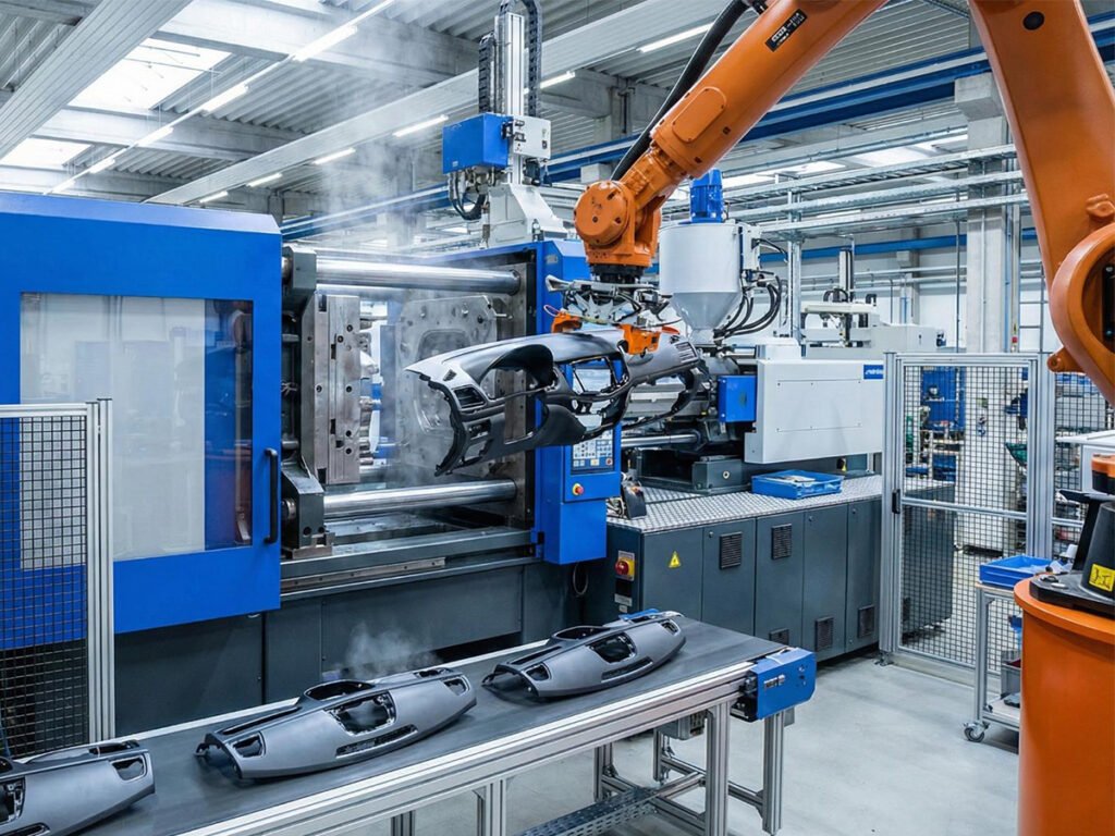
Molded threads are screw threads that are formed directly during the injection molding process, rather than being cut or machined after the part is produced. They are created as part of the mold cavity, meaning the thread geometry is defined by the tooling itself.
Unlike metal threads, molded threads must be designed with manufacturing constraints in mind, including mold release, material shrinkage, and flow behavior. As a result, they typically have more rounded profiles, controlled depths, and additional radii to ensure the part can be ejected from the mold without damage.
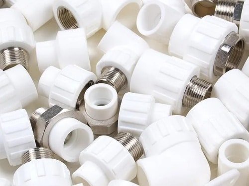
Molded threads are commonly used in plastic housings, caps, closures, and lightweight assemblies where integrated fastening is required without secondary machining.
Molded Threads vs CNC Threads
Molded threads and CNC threads achieve the same functional goal, but they differ significantly in how they are manufactured, which directly influences their design approach.
CNC threads are produced through material removal processes such as turning or tapping after the base material is formed. This allows for high precision, sharp thread profiles, and tighter tolerances. For a more detailed breakdown of different thread geometries, you can also refer to our guide on types of threads.
In contrast, molded threads are formed directly in the mold during injection molding, which introduces constraints that do not exist in CNC machining. For example, designers must account for draft angles, shrinkage, and mold parting direction. These limitations often result in slightly rounded thread profiles and more conservative dimensions compared to machined threads.
From a manufacturing perspective, CNC threading also offers more flexibility for post-processing adjustments, while molded threads are fixed once the mold is made. You can learn more about machining-based approaches in our article on CNC threading.
Key Parameters in Plastic Thread Design
When designing threads for injection-molded plastic parts, These parameters influence not only the mechanical strength of the threads but also the ease of manufacturing and long-term durability.
Thread Pitch
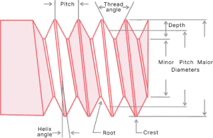
The thread pitch is the distance between adjacent thread crests, which influences holding power and moldability. Coarser threads are easier to mold and more robust in plastic, while finer pitches offer precision at the cost of mold complexity.
Thread Angle
The thread angle, often 60 degrees, is the angle between two adjacent thread surfaces. The thread angle determines how the load is distributed along the thread flanks.
Thread Depth
Thread depth is the distance from the crest to the root. It affects the engagement and holding power of the thread. Deeper threads offer greater holding strength but can introduce stress concentrations in surrounding plastic, especially in thin-walled components.
Major, Minor, and Pitch Diameters
The major diameter is the crest outermost diameter of the thread, the minor diameter is the root innermost, and the pitch diameter is the effective diameter between them. They must be coordinated with mating elements for proper fit and strength.
Helix Angle
The helix angle defines the inclination of the thread around the core. A moderate helix angle improves assembly ease while minimizing deformation during installation. Excessive helix angles can lead to uneven engagement and difficulty in demolding.
Crest and Root Geometry
Sharp thread crests and roots concentrate stress and can cause cracks or breakage. For plastic threads, rounded crests and roots are recommended. This approach reduces stress concentrations, facilitates molding, and improves part longevity.
Recommended Materials for Molded Plastic Threads
Material selection strongly influences thread performance. The common plastic materials are:
POM: POM offers great creep resistance, low friction, high stiffness, and good dimensional stability. Acetal threads maintain their shape under sustained torque and exhibit minimal wear when mated with metal fasteners.
Nylon 6/6: Nylon provides good toughness and flexibility. It absorbs assembly stresses well and resists cracking during screw insertion. Nylon is suitable for internal threads and self-tapping bosses.
ABS: ABS is cost-effective, easily molded, and finishes well. They are commonly used for non-critical, lightly loaded threads.
PC: Polycarbonate delivers high impact strength and transparency, but it is prone to stress cracking under sustained load. Polycarbonate threads are often found in optical or display-related housings.
PP: Polypropylene has lower strength, chemical resistance, and a lower price. It is occasionally selected for large, coarse threads in disposable or low-cost items.
Design Considerations for Molded Threads
Unlike metal threads, plastic threads are more prone to stripping, cracking, and deformation. Designing molded threads for plastic parts requires careful attention to material properties, geometry, and manufacturing constraints.
1. Thread Size and Pitch
Plastic threads should generally use coarse pitch to reduce stress concentration and improve manufacturability. Internal threads should be at least 2 mm in diameter, external threads at least 4 mm, and the engagement length should not exceed 1.5–2 times the thread diameter. This helps reduce pitch errors and improves reliability.
2. Wall Thickness and Geometry
The surrounding wall should at least match the thread depth, ideally 1.5 times the minor diameter. Avoid sudden thickness changes, which may introduce molded-in stress. If the thread ends near a load-bearing flange, add a smooth radius transition to reduce stress buildup.
3. Crest and Root Design
Avoid sharp edges. Rounded crests and roots reduce stress concentration and lower the risk of cracking. Even with rounding, the thread root remains a weak area, so the overall part geometry and adjacent structures should help distribute load.
4. Draft Angle and Undercuts
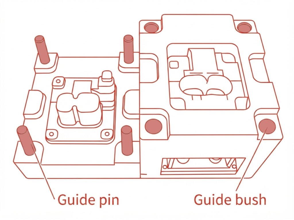
Include 1–2 degrees of draft for easier demolding. Threads are undercuts, especially internal ones, so collapsible cores or side actions may be required. These solutions increase tooling cost but ensure accurate injection molding thread design.
5. Material Selection
Material choice directly affects thread performance. ABS, POM, and nylon are reliable options for internal threads because they resist stress cracking and maintain dimensional stability. For applications requiring repeated tightening or high strength, consider reinforced grades or using metal inserts.
6. Thread Termination and Stops
Thread ends are critical points for stress concentration. Avoid designing the thread to end directly into a tool groove or transition cone. Include a non-threaded margin of 0.2–0.8 mm at the start and end of threads to prevent cracking and deformation.
7. Assembly Considerations
Plastic threads must be designed considering the mating part. Avoid pairing metal male threads with plastic female threads unless the design includes reinforcement. Ensure consistent pitch and rotation direction when using multiple thread segments, especially for unscrewing mechanisms.
8. Best Practices Summary
- Use coarse pitch and maintain minimum thread diameters for strength.
- Ensure uniform wall thickness and smooth transitions near threads.
- Round crests and roots to reduce stress.
- Apply draft angles to facilitate demolding.
- Select materials suitable for intended loads, repeated use, and environmental conditions.
- Include thread stops and non-threaded margins at terminations.
- Consider inserts or segmenting for high-stress or complex threads.
Alternatives to Direct Molded Threads
In some cases, designing thread features directly into the molded part is not the most practical solution. Alternative solutions are available:
- Post-Mold Machining: Cut or tap threads after molding. Best for prototypes and low-volume production.
- Self-Tapping Screws: For components designed with pre-formed holes or bosses, self-tapping screws can cut threads in situ, reducing mold complexity.
- Metal Thread Inserts: Provide high strength, wear resistance, and repeated-use durability. Can be overmolded during injection or installed post-molding.
- Snap-Fits and Quarter-Turn Fasteners: Eliminate threads for permanent or semi-permanent assemblies.
Conclusion
Molded threads require a design approach that balances function, manufacturability, and long-term performance. Unlike machined threads, they must account for molding constraints such as draft angles, shrinkage, and mold release, which makes early-stage design decisions especially important.
If you are working on products that require reliable threaded components, our custom injection molding service can support you from design optimization to mass production, helping ensure that your thread structures are both manufacturable and cost-efficient.
At Zhongde, we focus on delivering practical engineering solutions backed by real production experience. Feel free to contact us to discuss your project and see how we can help turn your design into stable, production-ready parts.