“Interference fit” isn’t a specific assembly method—it’s a dimensional relationship in which one part is slightly larger than the space it fits into. That small difference in dimensions creates a solid connection, even before any press or heat is applied.
Behind this simple principle are molding parameters, dimensional calculations, and practical assembly considerations—what this article explores.
What Is an Interference Fit?
An interference fit exists when a part’s dimension is slightly larger than the space designed to receive it—commonly a shaft and bore, but the same principle applies to bosses, pins, bearings, and molded inserts. This is a deliberate dimensional relationship, designed to create enough radial pressure for a secure, self-retaining joint. The dimensions define the fit, while the design requirements determine whether it performs as intended.
Types of Fit
Interference fit is best understood alongside its counterparts. Engineering practice generally recognizes three categories of fit, each defining a different relationship between mating parts:
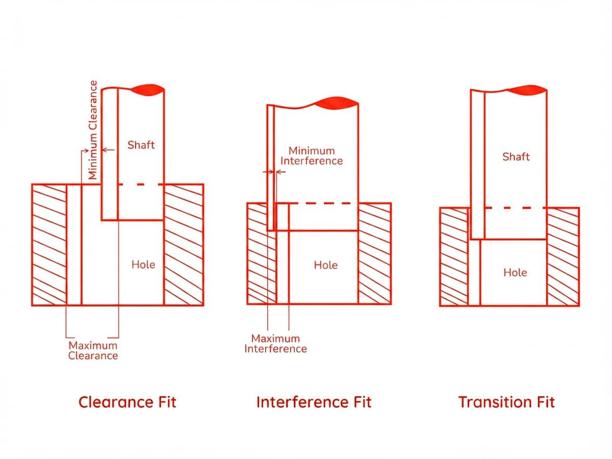
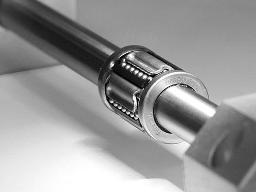
- Clearance fit – the shaft is always smaller than the bore, leaving a gap for free movement. Example: a rotating shaft inside a plain bearing.
- Transition fit – the fit may have either slight clearance or slight interference, depending on tolerance variation. Example: a dowel pin used for accurate alignment but occasional disassembly.
- Interference fit – the shaft is always larger than the bore, requiring force to assemble and creating a secure, self-retaining joint. Example: a bearing race pressed into a housing.
Interference fit is one of three common fit types. See our guide to types of fit for a broader comparison.
When to Use Interference Fit
Choosing an interference fit depends on how the joint needs to perform and behave over time. Several conditions typically point toward this type of fit:
When Long-Term Assembly Is the Goal
Parts designed to remain together throughout the product’s service life, without screws, adhesives, or welds, can benefit from the mechanical grip provided by an interference fit.
When Load Transfer Matters
Gears, pulleys, and bearings mounted on shafts often use interference fits to transmit torque or radial loads through friction, without additional locking features.
When Sealing or Vibration Resistance Is Needed
Continuous contact pressure can help resist loosening under vibration and contribute to sealing in certain housing applications.
When Space or Weight Is Limited
Eliminating fasteners can simplify assembly and reduce the number of components, which is useful in compact or lightweight designs.
How to Calculate Interference
Before assembly begins, the amount of interference must be determined—the difference between the shaft’s outer dimension and the bore’s inner dimension. This value must be controlled carefully: too little interference can cause the joint to loosen under load, while too much can create excessive stress, leading to housing cracks or shaft deformation.
The calculation also needs to account for material properties, part geometry, applied loads, manufacturing tolerances, and operating temperature. These factors affect the contact pressure, resulting stress, friction capacity, and thermal expansion of the joint.
The calculation typically follows these steps:
Step 1 — Interference (δ)
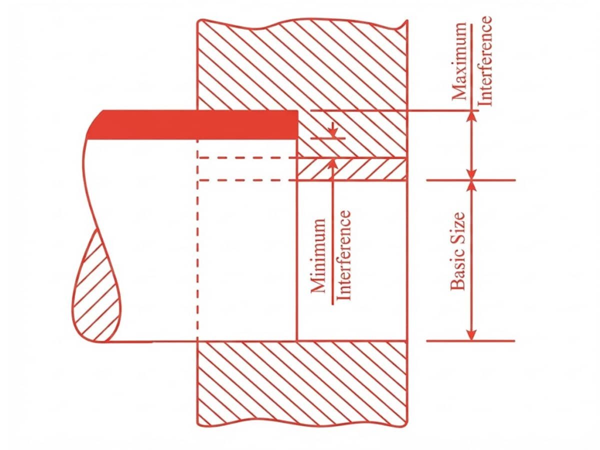
The calculation starts with the interference (δ), the amount by which the shaft’s outside diameter exceeds the bore’s inside diameter:
δ = D_shaft − D_bore
Both diameters carry manufacturing tolerances, so a real joint has a range of interference values. The two limits are:
δ_max = D_shaft,max − D_bore,min
δ_min = D_shaft,min − D_bore,max
Both limits are based on the nominal diameter, or basic size, shared by the shaft and bore. δ_max determines the upper end of the interference range and the resulting contact pressure and stress, while δ_min determines the lower end and the minimum contact pressure available to resist slip. Together, they define the full tolerance range of the fit.
Step 2 — Contact Pressure (p)
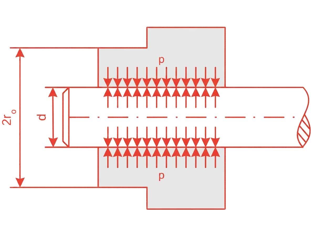
With the interference range known, the contact pressure (p) at the interface follows from Lamé’s equations for thick-walled cylinders. The result depends on the geometry and elastic properties of both parts. Pressure is assumed uniform along the fit length, as shown in the diagram:
p = δ / [ (d/E_o) × ((r_o² + r_i²)/(r_o² − r_i²) + ν_o) + (d/E_i) × ((r_i² + r_c²)/(r_i² − r_c²) − ν_i) ]
Where:
- d = nominal fit diameter (d = 2r_i)
- r_o = outer radius of the hub (hub outer diameter = 2r_o)
- r_i = interface radius
- r_c = inner radius of the shaft (r_c = 0 for a solid shaft)
- E_o, E_i = elastic modulus of the hub and shaft
- ν_o, ν_i = Poisson’s ratio of the hub and shaft
For a solid shaft and a hub made of the same material (E_o = E_i = E), r_c = 0, and the Poisson terms cancel, giving:
p = (E × δ) / [ d × ((r_o² + r_i²)/(r_o² − r_i²) + 1) ]
This can also be written using the hub outer diameter D₂ = 2r_o:
p = (E × δ / 2d) × (1 − (d/D₂)²)
Use δ_min and δ_max from Step 1 to determine the minimum and maximum contact pressure of the joint.
Step 3 — Stress (σ)
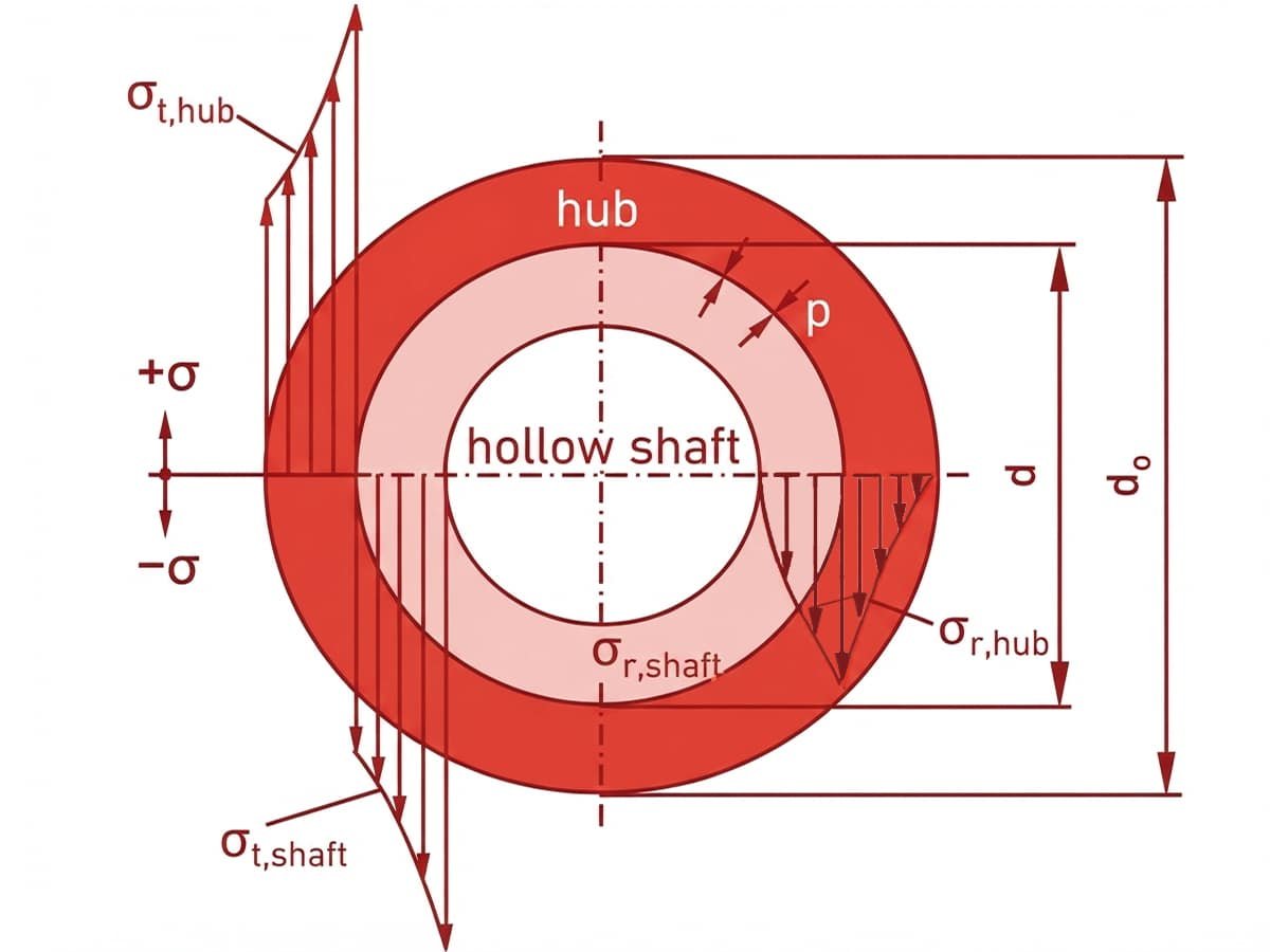
The contact pressure p from Step 2 loads both parts. In the idealized model, the hub is stretched in the tangential direction (tension, positive in the diagram), while the shaft is compressed (negative). Hoop stress reaches its maximum magnitude at the hub bore and at the inner surface of a hollow shaft. Use the pressure from δ_max in Step 1 to evaluate the highest stress.
Hub, at the bore:
σ_t,hub = p × (d_o² + d²) / (d_o² − d²)
Hollow shaft, at its inner surface (d_c = 2r_c):
σ_t,shaft = −2p × d² / (d² − d_c²)
The radial stress equals −p at the interface on both sides. It falls to zero at the outer surface of the hub and, for a hollow shaft, at its inner surface. A solid shaft has σ_t = σ_r = −p throughout, so only the hub formula needs checking.
Compare σ_t,hub and |σ_t,shaft| with the yield strength of each material, applying an appropriate safety factor, to verify that neither part undergoes excessive plastic deformation.
Step 4 — Friction capacity (F, T)
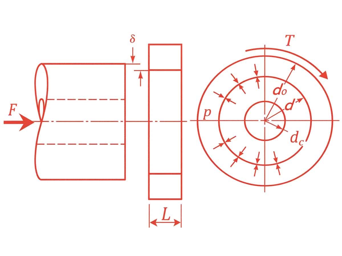
With the contact pressure established, the friction capacity of the joint follows from the pressure acting over the mating surface. The axial friction force F is:
F = μ × p × π × d × L
The torque T that the joint can transmit is:
T = F × d/2 = μ × p × π × d² × L / 2
Where:
- μ = coefficient of friction between shaft and hub
- p = contact pressure from Step 2
- d = nominal fit diameter
- L = length of engagement
Use the pressure from δ_min in Step 1 to determine the minimum friction capacity. The same relationship gives the maximum press-in force at δ_max, assuming the same friction coefficient and uniform contact pressure.
Compare F and T with the axial load and torque the joint must carry, applying an appropriate safety factor. If the capacity is insufficient, increasing the interference or engagement length can increase friction capacity, but any increase in interference should be checked against the stress limits in Step 3. Additional features such as keys or adhesives may also be considered.
Step 5 — Thermal effects (ΔT)
If the joint requires heating the outer part or cooling the inner part for installation, the required temperature change can be calculated from the interference determined in Step 1:
ΔT = δ / (α × d)
Where α is the coefficient of thermal expansion of the relevant material. This determines the temperature change needed to create sufficient clearance for assembly.
Interference Fit for Plastic Parts
Plastic parts require more careful interference-fit design because their material behavior differs significantly from metals. When designing a plastic interference fit, consider:`
- Lower stiffness: A lower elastic modulus means the same interference can produce lower contact pressure but greater deformation.
- Creep and stress relaxation: Under sustained pressure, many plastics gradually deform and lose contact pressure, reducing holding force over time.
- Temperature effects: Plastics can undergo relatively large dimensional changes with temperature, so interference should be checked across the expected operating temperature range.
- Molding variation: Shrinkage, moisture absorption, fiber orientation, and dimensional tolerances can affect the actual interference in molded parts.
- Material selection: Interference should be selected based on the plastic’s modulus, yield strength, creep behavior, temperature range, and geometry rather than directly applying values intended for metal parts.
How to Specify Interference Fit on a Drawing
Once the calculations are complete, the results need to be translated into CNC standard tolerances or other tolerance callouts that a machinist or supplier can work from—usually through the ISO fit system or direct dimensional limits.
Using the ISO Tolerance System
Interference fits are commonly specified using a hole/shaft tolerance pair, such as H7/p6. The capital letter and number define the hole tolerance, while the lowercase letter and number define the shaft tolerance. For example, a ⌀20 H7 bore paired with a ⌀20 p6 shaft is designed to produce interference across the specified tolerance range.
Using Direct Dimensional Limits
When ISO codes aren’t practical—for molded or non-standard parts, for example—the drawing can state the upper and lower limits directly:
Bore: ⌀20.000–20.021 mm
Shaft: ⌀20.035–20.048 mm
These dimensional limits define the press fit tolerances, ensuring that the shaft remains larger than the bore across the specified range.
Common Assembly Methods for Interference Fit
Once the interference is established, the next question is how to physically join the two parts. The interference fitting method depends on the interference amount, part geometry, and material.
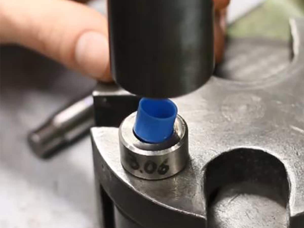
Press Fitting
Force is applied directly, typically with a hydraulic or arbor press, to push the shaft into the bore at room temperature. Press fits are commonly used when the required assembly force remains within a safe range for both parts.
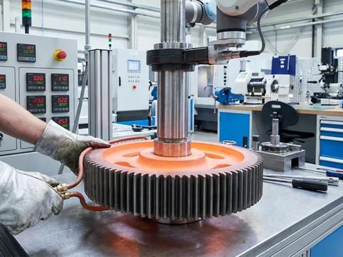
Shrink Fitting
The outer part is heated to expand its bore temporarily, allowing the shaft to slide in with little or no force. As it cools, the bore contracts and grips the shaft. This is useful for larger interference values or parts that could be damaged by high press forces. Example: fitting a gear onto a shaft in heavy machinery.
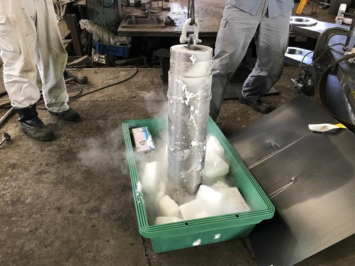
Cold Fitting (Expansion Fitting)
The inner part is cooled, often with dry ice or liquid nitrogen, so it contracts and can be inserted with minimal force. This is useful when heating the outer part isn’t practical, such as with heat-sensitive materials or coatings.
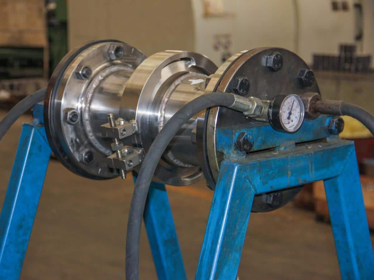
Hydraulic Assembly
A thin film of oil is injected at the interface under pressure, temporarily reducing friction so the parts can slide together. The oil is then removed after assembly. This method is useful for large interference fits where mechanical force alone would be impractical.
Common Problems in Interference Fit Assembly
Precise calculations and a suitable assembly method reduce risk, but problems can still occur during assembly.
Galling or Scoring During Press Fitting
Friction between mating surfaces can cause scratching or galling, especially with softer metals. Lubricating the interface or switching to thermal or cold fitting can reduce insertion force and surface damage.
Cracking or Yielding of the Outer Part
Excessive interference can generate stress beyond the material’s yield strength, cracking brittle parts or permanently deforming ductile ones. Check the calculated pressure and stress against the material limits, and adjust the tolerance range if necessary.
Insufficient Holding Force
If the interference is too small, or oil or debris contaminates the mating surfaces, the joint may loosen or slip under load. Clean the surfaces and confirm that the actual interference meets the calculated minimum.
Misalignment During Insertion
Pressing a shaft in at an angle can damage the bore or shaft edges. Use guide chamfers on the leading edges and proper alignment fixtures during assembly.
Uneven Temperature During Shrink Fitting
If the outer part cools unevenly before the shaft is fully seated, the fit can lock prematurely in a misaligned position. Work quickly and use controlled, uniform heating to reduce this risk.
Applications of Interference Fit
Interference fits are widely used where parts need to stay securely positioned without relying on fasteners. They do not always mean permanent assembly; many interference-fit components are designed to be removed for maintenance or replacement.
- Bearings – inner and outer races fitted onto shafts or into housings for secure, load-bearing rotation.
- Gears and pulleys – mounted on shafts to transmit torque through friction.
- Bushings and sleeves – installed in housings for wear resistance, alignment, or dimensional support.
- Automotive components – valve seats, wheel studs, and gear assemblies use interference fits to withstand vibration and load.
- Electric motors – rotor cores and shafts joined through interference fits to maintain concentricity and transmit rotational force.
- Molded plastic assemblies – inserts or bosses designed with interference to reduce or eliminate the need for adhesives or screws.
Conclusion
A reliable interference fit depends on controlled dimensions, suitable materials, and proper assembly methods. For precision shafts, bores, and other mating components, Zhongde CNC machining services provide the dimensional accuracy needed to produce consistent interference fits.