Machining surface finish is a fundamental aspect of manufacturing that defines a part’s texture, functionality, and aesthetic appeal of machined parts. This article explores what machining surface finish is, why it matters, the levels of CNC surface finish achievable, and how machining surface roughness is measured, with an emphasis on practical insights and industry standards.
What Is Machining Surface Roughness?
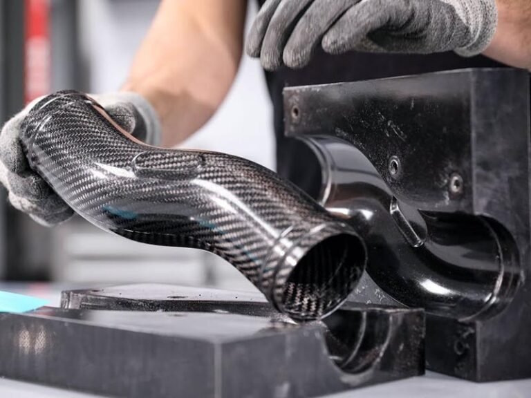
Machining surface roughness refers to the microscopic deviations and irregularities on a machined surface after CNC processes like milling, turning, or grinding. These deviations, often invisible to the naked eye, determine how smooth or coarse a surface feels and performs.
In CNC surface finishing, roughness is quantified using parameters like Ra (arithmetic mean roughness), Rz (maximum height of the profile), and Rq (root mean square roughness). Ra, the most common metric, measures the average deviation from the mean surface line, expressed in micrometers (µm).
Learn More: What is CNC Machining?

Why Is Machining Surface Roughness Important?
The importance of machining surface finish extends far beyond mere appearance. It significantly impacts the functional performance, durability, and reliability of machined components across industries.
Reduced Friction and Wear: Smoother surfaces reduce friction in moving parts like gears or bearings, which decreases wear and extends the lifespan of components such as bearings, gears, and pistons. A rough milled surface finish increases wear, leading to premature failure.
Improved Fatigue Strength: Rough surfaces can act as stress concentrator, leading to premature failure under cyclic loading. A well-controlled surface finish distributes stress more evenly, enhancing fatigue life.
Enhanced Durability and Corrosion Resistance:Fine surface finishes minimize surface defects and irregularities where corrosive agents can accumulate, thereby improving corrosion resistance and overall durability.
Better Adhesion of Coatings: Surface texture influences how coatings or paints adhere to a part. Appropriate surface roughness ensures coatings bond effectively, improving protection and appearance.
Optimized Sealing: In applications involving gaskets or O-rings, the surface finish is critical to ensure proper sealing and prevent leaks.
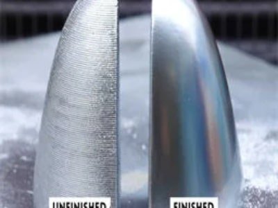
Aesthetic Appeal and Consumer Perception: A high-quality surface finish enhances the visual appeal of products, which is crucial in consumer electronics, automotive, and aerospace industries.
CNC Surface Roughness Levels
CNC surface roughness levels are quantified primarily by Ra and Rz values, with typical ranges from 3.2 µm Ra for standard parts to below 0.4 µm Ra for precision applications. Here is a table to compare the differences between different levels:
| Surface Roughness Level (Ra) | Characteristics | Applications | Processing Considerations |
|---|---|---|---|
| 3.2 µm Ra (Standard) | Moderate roughness, typical commercial finish. | General-purpose CNC machined parts, housings, brackets. | Balanced feed rates and speeds, often no additional finishing. |
| 1.6 µm Ra (Fine) | Smooth surface with minor visible texture. | Automotive components, consumer products, parts requiring better fit. | Slower feed rates, sharper tools, possible polishing. |
| 0.8 µm Ra (Very Fine) | Fine tooling, controlled speeds, often followed by polishing or grinding. | Aerospace parts, medical devices, precision instruments. | Very smooth surface, minimal texture. |
| 0.4 µm Ra and below (Ultra Fine) | Mirror-like finish, almost no visible texture. | Optical components, high-precision molds, sealing surfaces. | Specialized tooling, slow cutting speeds, multiple finishing steps. |
How to Choose the Right CNC Surface Roughness?
The right CNC surface finish ensures a part meets its performance goals and standard machining tolerance without inflating production costs. It should achieve a balance of function, material, cost, and manufacturing constraints.
Consider Functional Requirements: Start by assessing the part’s role. Sliding components, like bearings or pistons, need lower Ra values to minimize friction and wear. Static parts, like structural supports, can tolerate rougher grades without compromising performance.
Account for Aesthetics: If a shiny, polished, or reflective finish is desired—such as for consumer products, decorative parts, or visible housings—a low Ra value (0.8 µm or below) is recommended. Conversely, if a textured or matte look is preferred, higher Ra values (1.6 µm and above) can be specified.
Evaluate Cost Trade-Offs: Achieving smoother surfaces requires more machining effort, including slower cutting speeds, finer feed rates, shallower cuts, and sometimes additional finishing processes like polishing or grinding.
Consider Material Properties: Material hardness affects achievable roughness. Softer materials like aluminum or brass support finer machined surface roughness (N3–N4), while harder materials like titanium may limit finishes to N6 unless secondary processes are used.
Check Industry Standards: Industries like aerospace or medical often mandate specific roughness grades. Always review project specifications for compliance.
Match the CNC Process: Different processes and parmaeters yield distinct roughness levels.
- Cutting speed: Higher speeds generally reduce roughness but excessive speed can increase friction and roughness.
- Feed rate: Lower feed rates allow the tool more time to cut smoothly, producing finer finishes.
- Cut depth: Shallower cuts reduce tool vibration and deflection, improving surface quality.
How is Surface Roughness Measured?
Contact Methods
The most common contact method is stylus profilometry, where a diamond-tipped stylus physically drags across the surface at a constant speed. As the stylus moves, it vertically displaces according to the surface irregularities, and this displacement is recorded by a high-resolution encoder. The collected data forms a surface profile, from which roughness parameters like Ra (arithmetic average roughness) are calculated.
Non-Contact Methods
Non-contact techniques use light or other probes to measure surface topography without physical interaction. Examples include:
- Optical Profilometry: Projects structured light or lasers onto the surface and captures the reflected pattern. Distortions in the reflected light reveal the surface texture, allowing calculation of roughness parameters.
- Atomic Force Microscopy (AFM): Uses a sharp cantilever probe that scans very close to the surface without touching it. Forces between the probe and surface cause deflections measured by a laser beam, enabling nanoscale roughness mapping.
- Laser Triangulation: Measures surface displacement by detecting the reflection angle of a laser beam as it scans the surface, generating a 3D surface map.
- Interferometry: Uses interference patterns of light waves to measure surface shape and texture with very high lateral and vertical resolution, suitable for detailed 3D roughness analysis.
Measurement Parameters
Surface roughness is quantified by parameters derived from the measured surface profile or area.
- Ra (Arithmetic Average Roughness): Average height of surface irregularities.
- Rz (Mean Roughness Depth): Average peak-to-valley height over several sampling lengths.
- Rt (Total Roughness): Maximum peak-to-valley height over the entire measured length.
Conclusion
Machining surface finish is more than a technical detail. It’s influencing a of CNC part performance from durability to aesthetics. To achieve the desired CNC finish, cooperate with experience manufacturer, choose the suitable CNC machining surface finish and achieve your project requirements. Zhongde supply CNC machining solutions tailored to your specific requirements. Welcome to contact our expert and get a professional solution.


