When designing plastic parts, achieving a reliable connection between components is often a key challenge. Traditional fastening methods such as screws and adhesives can increase assembly time, component count, and production costs.
Snap fits offer a way to integrate assembly features directly into plastic parts, but their performance depends heavily on material selection, geometry, and manufacturing considerations. Proper snap fit design helps achieve reliable assembly, reduce production costs, and improve the overall functionality of plastic products.
What Is a Snap Fit?
A snap fit is a mechanical fastening feature that allows two plastic components to be assembled by using the elastic deformation of the material. During assembly, one part temporarily bends or flexes to pass over another feature and then returns to its original position to create a secure connection.
A typical snap fit consists of a flexible section, such as a beam or arm, and an engagement feature that holds the connected parts together. Its performance depends on the relationship between material properties, deformation, and part geometry. Properly designed snap fits can provide secure connections while allowing controlled assembly and, in some cases, repeated disassembly.
Key Components of a Snap Fit
A snap fit usually consists of several structural features that work together to provide flexibility and locking force. Although the exact geometry varies depending on the application, most snap fits include a flexible section, a locking feature, and a connection area.
Beam
The beam is the flexible section of a snap fit that bends during assembly. Its length, thickness, and shape directly affect how much force is required for installation and how much stress the part experiences. A longer and thinner beam generally allows greater flexibility, while a shorter or thicker beam provides higher stiffness.
Hook
The hook is the locking feature that engages with the mating component. It creates the retention force that keeps two parts connected after assembly. The hook geometry, including the engagement depth and contact angle, influences both connection strength and ease of assembly.
Root Section
The root section is the area where the flexible beam connects to the main body of the part. Because this area experiences the highest stress concentration during bending, it is one of the most critical regions in snap fit design. Adding proper fillets and avoiding sharp corners can help reduce the risk of cracking or failure.
Engagement Area
The engagement area is the contact region between the snap fit and the mating component. Its dimensions affect the stability of the connection, assembly force, and ease of removal. Proper engagement ensures that the parts stay securely connected without making assembly unnecessarily difficult.
Types of Snap Fits by Shape
Snap fits can be designed in different shapes depending on the available space, required retention force, assembly direction, and expected service conditions. While some designs rely on bending beams, others use radial expansion or torsional movement to create engagement.
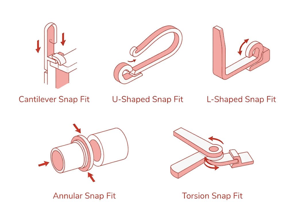
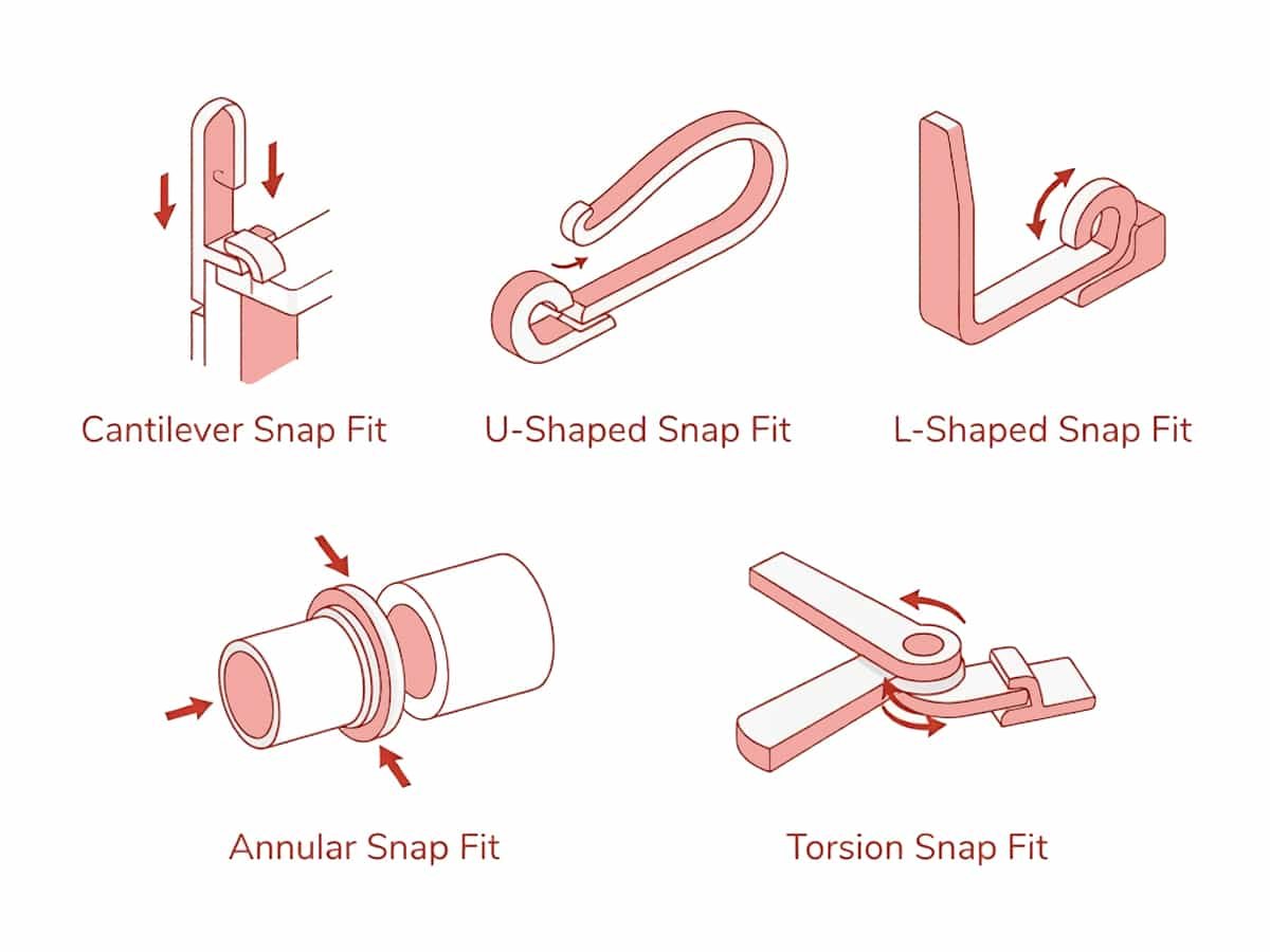
The most common snap fit shapes used in plastic part design include cantilever, U-shaped, L-shaped, annular, and torsion snap fits.
Cantilever Snap Fits
Cantilever snap fits are the most common type used in plastic part design. They consist of a flexible beam attached to the main body at one end, with a hook or locking feature at the other end. During assembly, the beam bends to allow the hook to pass through the mating component and then returns to its original position to create a connection.
Due to their simple structure and easy integration into injection molded parts, cantilever snap fits are widely used in housings, covers, electronic enclosures, and consumer products.
U-Shaped Snap Fits
U-shaped snap fits use a curved or U-shaped flexible section to provide additional movement compared with a straight cantilever design. The curved structure allows deformation to be distributed over a larger area, which can reduce stress concentration.
This design is useful when a longer flexible path is needed but the available installation space is limited. U-shaped snap fits are often used in compact plastic assemblies where flexibility and repeated engagement are important considerations.
L-Shaped Snap Fits
L-shaped snap fits use an L-shaped beam structure to create a locking feature while maintaining a compact layout. Compared with straight cantilever designs, the angled geometry changes the direction of force transmission and can provide more design flexibility in limited spaces.
They are often used when the snap feature needs to fit around existing structures or when the assembly direction does not allow a conventional straight beam design.
Annular Snap Fits
Annular snap fits use a circular design to create a locking connection between cylindrical components. They typically rely on radial deformation, where one component expands or compresses slightly during assembly before returning to its original shape.
This type of snap fit is commonly found in applications such as caps, containers, and cylindrical housings. Compared with cantilever designs, annular snap fits provide uniform engagement around the entire circumference, but they require more precise control of dimensions and tolerances.
Torsion Snap Fits
Torsion snap fits rely on rotational deformation rather than simple bending. A flexible element twists during assembly and stores torsional energy before returning to its original position to create the connection.
Compared with beam-based designs, torsion snap fits can provide controlled movement and good fatigue performance when properly designed. However, their geometry is usually more complex, making them less common in general plastic part applications.
Snap Fit Design Principles
Whether you are designing a cantilever, annular, or torsion snap fit, the same fundamental questions need to be considered: How much deformation is acceptable? How can stress be distributed effectively? How can the connection remain secure without making assembly difficult? Understanding these principles provides the foundation for making the right design decisions before optimizing specific parameters.
Design for Elastic Deformation
The basic function of a snap fit is to temporarily deform during assembly and return to its original shape after engagement. Therefore, the design should ensure that the deformation remains within the elastic range of the material.
A snap fit that is too rigid may require excessive assembly force, while one that is too flexible may not provide sufficient retention. The goal is to create enough movement for assembly without causing permanent deformation.
Control Stress Distribution
Snap fit failure usually occurs when stress is concentrated in a small area rather than distributed throughout the structure. Sharp corners, abrupt geometry changes, and improper transitions can create stress concentration points.
A good design should guide stress through the part structure smoothly and avoid localized loading areas that may lead to cracking or fatigue failure.
Balance Connection Strength and Usability
The purpose of a snap fit is not simply to maximize holding force. Excessive retention force can make assembly difficult and increase stress on the component.
A well-designed snap fit should provide enough locking strength for the application while maintaining acceptable assembly and, when required, disassembly performance.
Consider Manufacturing Constraints Early
A snap fit should be designed with the manufacturing process in mind from the beginning. Different production methods, including injection molding, 3D printing, and CNC machining, have different limitations in terms of achievable geometry, dimensional accuracy, and material behavior.
For injection molded parts, designers should pay particular attention to factors such as mold direction, draft angles, undercuts, and shrinkage. For prototypes or low-volume parts produced through other processes, factors such as layer orientation or machining limitations may also affect snap fit performance.
Design for the Intended Service Life
The expected usage condition should influence snap fit design decisions. A snap fit used once during assembly has different requirements from one that must be opened and closed hundreds or thousands of times.
Material behavior, environmental exposure, and repeated loading should all be considered to ensure the snap fit maintains reliable performance throughout its service life.
Cantilever Snap Fit Design
Among different snap fit structures, cantilever snap fits are the most widely used and well-established designs, especially in plastic part applications. Their simple structure makes it easier for engineers to analyze the relationship between material properties, beam geometry, deformation, and assembly force.
The following section focuses on cantilever snap fit design and explains how to evaluate and optimize its geometry for reliable performance.
Step 1: Select a Suitable Material
Material selection determines how much the snap arm can deform before permanent damage occurs. Since cantilever snap fits rely on elastic bending, the material should have sufficient allowable strain, fatigue resistance, and toughness.
Engineers usually refer to the material datasheet to find the allowable strain (ε), which defines the maximum deformation the snap arm can withstand without cracking.
Typical values vary depending on material grade and formulation. For example:
- Unfilled POM: approximately 4–8% allowable strain
- ABS: approximately 2%
- Glass-filled Nylon: approximately 0.5–1%
For snap fits requiring repeated assembly cycles, materials with good fatigue resistance, such as PP and POM, are often preferred. Materials with fillers may provide higher stiffness but usually allow less deformation.
Step 2: Define the Beam Geometry
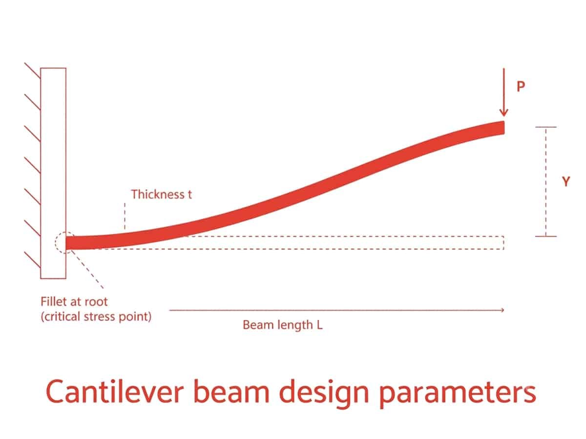
The dimensions of the cantilever beam determine its flexibility and required assembly force. The key parameters include:
- Beam length (L): A longer beam provides greater flexibility and reduces bending stress.
- Beam thickness (t): A thicker beam increases stiffness and required assembly force.
- Beam width (b): A wider beam increases load capacity but also increases stiffness.
As a general rule, designers should avoid making the beam unnecessarily short or thick because this concentrates stress near the fixed end and increases the risk of cracking.
Step 3: Calculate Allowable Deflection
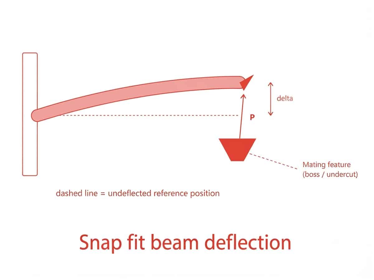
During assembly, the cantilever beam bends to allow the hook to pass over the mating feature. The required deflection should remain within the material’s allowable strain limit.
For a uniform rectangular cantilever beam, the maximum allowable deflection can be estimated as:
Y = (εL²) / (1.5 × t)
Where:
- Y = allowable deflection
- ε = allowable strain of the material
- L = beam length
- t = beam thickness at the base
This calculation helps determine whether the selected beam dimensions can achieve the required movement without exceeding the material’s elastic limit.
Step 4: Estimate Assembly Force
After determining the required deflection, engineers can estimate the force needed to bend the snap arm during assembly.
For a cantilever beam, the bending force can be approximated as:
P = (Ebtδ²) / (6L²)
Where:
- P = bending force
- E = modulus of elasticity
- b = beam width
- t = beam thickness
- δ = beam deflection
- L = beam length
The actual insertion force also depends on factors such as friction and the lead-in angle of the hook. Lower assembly force improves usability, but excessively low force may indicate insufficient retention strength.
Step 5: Optimize Hook and Angle Design
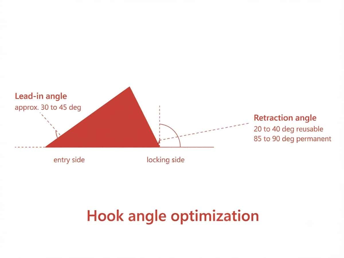
The hook geometry determines how easily the snap fit assembles and how securely it locks.
The main design factors include:
Lead-in angle
The entry side of the hook is usually designed with a gradual angle to reduce insertion force. A typical range is around 30°–45°.
Retraction angle
The locking side controls how easily the snap fit can be separated:
- Reusable snap fits: approximately 20°–40°
- Permanent snap fits: close to vertical (around 85°–90°)
A larger locking angle improves retention but increases the force required for removal.
Step 6: Reduce Stress Concentration
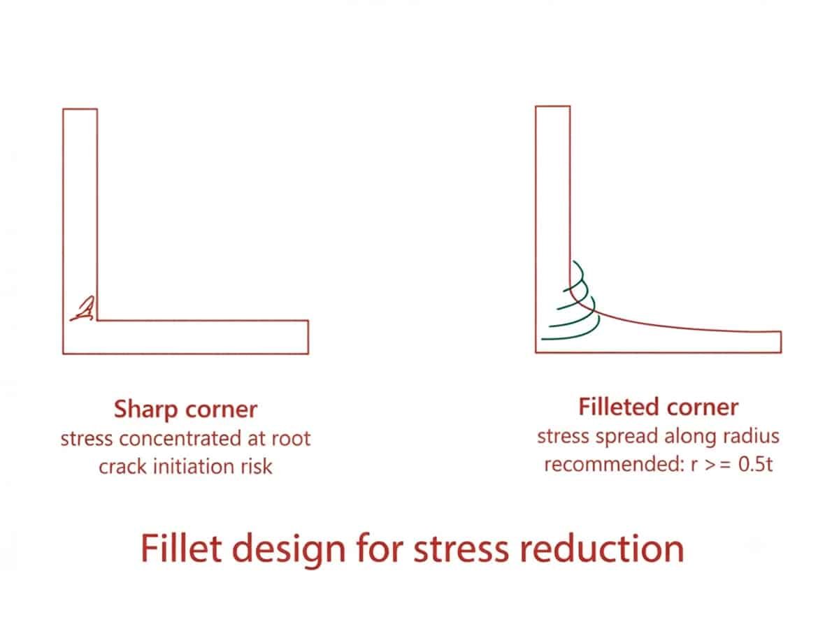
The root of the cantilever beam experiences the highest bending stress and is the most common failure location.
To improve durability:
- Add a fillet at the beam base.
- Avoid sharp 90° corners.
- Use gradual thickness transitions.
- Consider a tapered beam design to distribute strain more evenly.
A common starting point is a fillet radius of approximately 0.5 times the wall thickness, although the optimal value depends on the material and loading conditions.
Step 7: Consider Injection Molding Requirements
A cantilever snap fit must not only function mechanically but also be manufacturable.
During injection molding design:
- Keep the snap arm aligned with the mold opening direction when possible.
- Avoid unnecessary undercuts that require complex tooling.
- Maintain consistent wall thickness to reduce warpage.
- Add draft angles on non-functional surfaces for easier ejection.
If the snap arm requires side actions or lifters, tooling complexity and cost may increase.
Common Snap Fit Failures and Troubleshooting Methods
Even with careful design calculations and proper material selection, snap fits may still experience performance issues during prototyping or production. These problems are often related to excessive stress, insufficient engagement, material behavior, or manufacturing variation. Identifying the symptom is the first step toward finding the right solution.
| Symptom | Most Likely Cause | First Fix to Try |
|---|---|---|
| Breaks on first snap | Strain exceeds allowable limit | Add fillet, lengthen/taper beam |
| Pops open under load | Retraction angle/depth too shallow | Increase angle toward 90° (permanent) |
| Hard to assemble | Lead-in angle too steep / high friction | Reduce lead-in angle, reduce friction |
| Rattles over time | Creep / continuous stress after assembly | Redesign so beam is unstressed when engaged |
| White stress marks | Sharp corner / high local strain | Add/increase fillet radius |
| Won’t release | Angle designed as permanent | Reduce retraction angle, add release tab |
| Inconsistent fit batch to batch | Molding/tooling variation | Uniform wall thickness, tooling maintenance |
| Fails after many cycles | Fatigue strain exceeded | Use cyclic allowable strain, add fillet |
Snap Fits Manufacturing Process
Snap fits can be produced using different manufacturing methods depending on the required material, production volume, part complexity, and performance requirements. Although injection molding is the most common process for plastic snap fit parts, other manufacturing methods can also be used for prototyping, low-volume production, or specific application requirements.
Injection Molding
Injection molding is the most common manufacturing method for snap fits used in mass-produced plastic parts. It allows snap features to be molded directly into the component with consistent dimensions and good repeatability.
Injection molded snap fits are widely used for products such as electronic housings, automotive interior components, and consumer products. When designing these features, factors such as mold release direction, draft angles, parting lines, and material shrinkage should be considered to ensure smooth ejection and reliable assembly.
3D Printing
3D printing is often used for prototyping snap fit designs before moving to mass production. It allows designers to quickly test different geometries and evaluate assembly performance without investing in injection molds.
However, the performance of 3D printed snap fits may differ from injection molded versions due to differences in material properties, layer orientation, and surface finish. Designers should consider these factors when testing functional prototypes.
For more details about related design considerations, see our guide on How Do You Design 3D Print Snap Fit Joints.
CNC Machining
CNC machining can be used to create snap fit prototypes or low-volume parts, especially when working with engineering plastics. It provides high dimensional accuracy and allows designers to test the fit and function of a component before committing to injection molding.
However, CNC machining is generally less suitable for complex snap fit geometries or large-scale production because the process removes material instead of forming integrated features directly into the part.
Benefits of Snap Fits
Beyond simplifying assembly, snap fits provide several functional advantages that make them suitable for a wide range of plastic part applications. When properly designed, they can improve product performance, user experience, and overall design flexibility.
Lightweight Structure
Snap fits eliminate the need for additional fastening components such as screws, nuts, or metal brackets. This helps reduce the overall weight of plastic assemblies, which is especially valuable in applications where weight reduction is important, such as consumer electronics, automotive components, and portable devices.
Better Material Integration
Since snap fits are molded as part of the plastic component, their performance can be optimized together with the material selection. Designers can choose materials with suitable flexibility, fatigue resistance, and strength to match the expected loading conditions.
Easy Maintenance and Serviceability
Some snap fit designs allow parts to be repeatedly assembled and disassembled without damaging the components. This is useful for products that require access to internal parts, such as battery compartments, electronic housings, and protective covers.
Improved Product Appearance
Snap fits can provide a cleaner appearance by avoiding visible screws, holes, or external fastening elements. For consumer products and other appearance-sensitive applications, this helps maintain a smooth and streamlined surface design.
Limitations of Snap Fits
Although snap fits offer many advantages in plastic part design, they are not suitable for every application. Their performance is highly dependent on material properties, geometry, and operating conditions. Understanding these limitations helps designers avoid premature failure and select the right fastening method.
Limited Load-Bearing Capacity
Snap fits are generally designed for light to moderate loads rather than applications requiring high mechanical strength. Continuous heavy loads or excessive external forces can cause deformation, loosening, or failure of the locking feature.
Material Selection Constraints
The flexibility required for snap fits limits the range of suitable materials. Brittle plastics with low elongation may crack during assembly, while materials with poor fatigue resistance may fail after repeated use. Material properties such as elasticity, creep resistance, and environmental stability must be considered during design.
Sensitivity to Dimensional Changes
Snap fits often require precise control of dimensions and tolerances. Variations caused by material shrinkage, temperature changes, or manufacturing inconsistencies can affect assembly force and connection reliability. This is especially important for injection molded parts, where process parameters can influence final dimensions.
Difficulties in Repeated Assembly
Not all snap fits are designed for multiple assembly cycles. Repeated bending and stress release can gradually reduce material performance, causing the snap feature to lose its holding force or develop cracks over time.
Increased Mold Complexity for Certain Designs
Although snap fits can simplify part assembly, complex geometries may increase mold design challenges. Features with deep undercuts or difficult release directions may require additional tooling solutions, such as slides or lifters, which can increase mold complexity and cost.
Applications of Snap Fits
Snap fits are widely used in products that require lightweight assembly, compact structures, or easy access to internal components. Because they can be integrated directly into a part, they are commonly found in everyday consumer products, electronic devices, automotive components, and industrial equipment.
Consumer Electronics
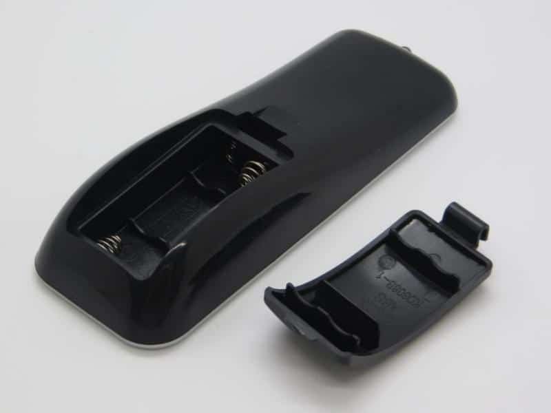
Many consumer electronic products use snap fits to join plastic housings without visible fasteners. Common examples include remote controls, wireless earbuds cases, keyboards, and small electronic enclosures.
Snap fits allow these products to maintain a clean appearance while keeping the housing lightweight. For components such as battery covers or removable panels, snap fits can also provide convenient access for replacement or maintenance.
Automotive Interior Components
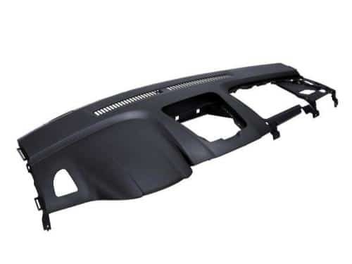
Automotive interiors contain many plastic parts assembled with snap fits, including trim panels, instrument panels, storage compartments, and cable management components.
In these applications, snap fits help reduce the number of separate fasteners while allowing efficient assembly of complex interior structures. The design must also consider vibration, temperature changes, and long-term durability.
Household Products
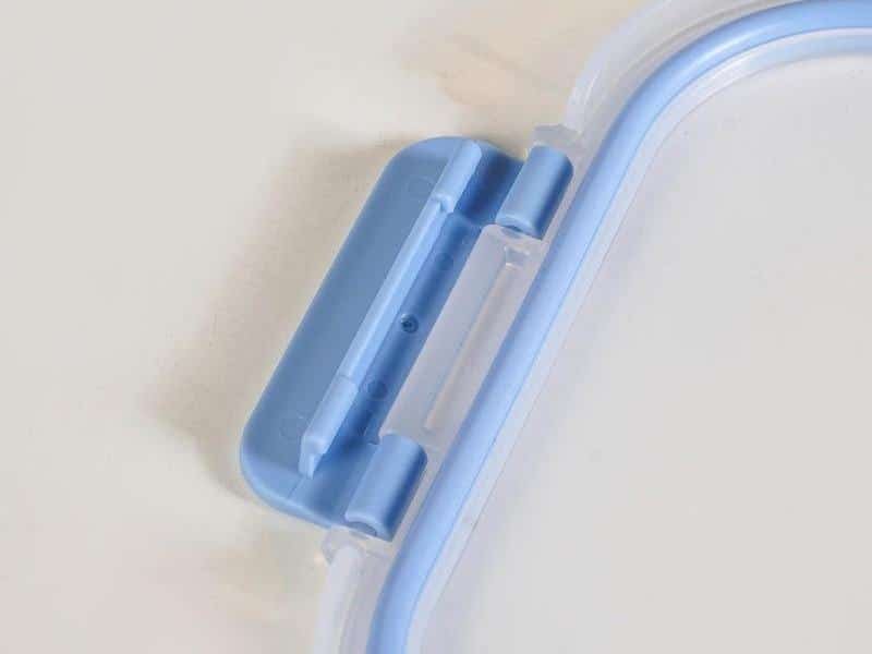
Many household products use snap fits in covers, lids, and protective housings. Examples include storage containers, small appliances, vacuum cleaners, and kitchen equipment.
These applications often require a balance between secure connection and user-friendly operation. For frequently opened components, designers need to consider repeated assembly cycles and material fatigue.
Medical Devices and Equipment
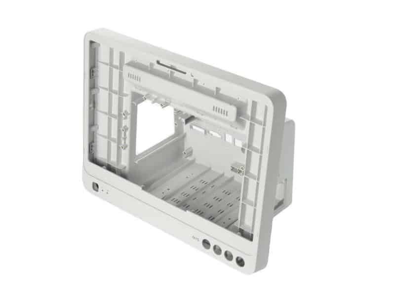
Snap fits are also used in certain medical devices and equipment housings where lightweight construction and compact assembly are important.
For these applications, designers must carefully evaluate material compatibility, cleaning requirements, dimensional stability, and reliability throughout the product lifecycle.
Conclusion
Designing a reliable snap fit requires more than adding a locking feature to a part. As you have learned throughout this guide, successful snap fits depend on the right combination of structure, material behavior, deformation control, and manufacturing considerations.
If you are developing plastic parts with snap fit features, Zhongde can help review your design, optimize manufacturability, and provide reliable custom injection molding services from prototype to production.