Ejector pin marks are common defects in injection molding processes and significantly impact the quality and appearance of molded parts. Ejector pin marks typically appear on the surface of molded parts at the points where the ejector pins make contact during the ejection process. In this post, we will explore the causes of ejector pin marks and learn how to prevent ejector pin marks in injection molding.
What are Ejector Pin Marks?
Ejector pin marks are visible defects or blemishes that appear on the surface of injection-molded plastic parts. Ejector pin marks defect typically look like glossy or white imprints, indentations, depressions, or varying levels of glossiness (dark or shadow-like areas) on the part’s surface, directly opposite the location where the ejector pins contacted the part during ejection from the mold cavity.

What Do Ejector Pin Marks Look Like?
Ejector pin marks on plastic product are visible indentations, depressions, or blemishes on the surface of an injection molded plastic part. They can manifest in different ways:
Shallow Indentation Marks
These appear as small indentations or dimples in the shape of the ejector pin, typically on the surface that contacts the ejector pin during ejection from the mold. Positional deviations of the ejector pin cause them.
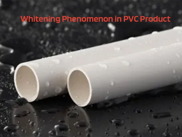
Whitening or Glossy Marks
In these cases, the color at the ejector pin area becomes lighter or glossier, forming white spots or halos. These can appear on both the surface contacting the pin and the opposite side. They are caused by stress exerted during ejection or temperature differences.
Discolored Marks
The area around the ejector pin may appear slightly discolored compared to the surrounding areas, often appearing shinier.
How do Ejector Pin Marks Affect the Molded Parts?
Ejector pin marks can have several detrimental effects on injection molded plastic parts:
Aesthetic Issues
Ejector pin marks appear as visible blemishes, indentations, or discolorations on the surface of the part, compromising its aesthetic appeal.
They create an uneven or rough surface texture, affecting the tactile feel and perceived quality of the product.
Functional Impairment
If located in critical areas, ejector marks can interfere with the part’s intended function, hindering proper assembly or operation of moving components.
They can affect the fit and compatibility with other mating parts.
Structural Integrity Concerns
Ejector pin marks indicate localized areas of stress concentration or deformation on the part.
These stress concentrations can weaken the structural integrity, making the part more susceptible to cracking, failure or reduced durability over time.
Inconsistency in Product Quality
Inconsistent occurrence of ejector pin marks across a production batch can lead to variations in product quality and appearance.
This lack of consistency can be problematic, especially for applications requiring tight tolerances or high cosmetic standards.
Potential for Further Damage
Ejector pin marks can create potential crack initiation sites, increasing the risk of further damage or failure during the product’s service life.
What Causes Ejector Pin Marks In Injection Molding?
Product Design Issues:
- Insufficient wall thickness: Excessively thin wall thickness, especially for complex geometries with ribs/bosses (generally <2.5mm for simple parts, <2.8mm for complex parts).
- Lack of adequate draft angles or uniform wall thickness: Insufficient draft angles or non-uniform wall thickness can cause parts to stick to the mold, requiring higher ejection force and potentially causing ejector pin marks.
- Presence of ribs, bosses, or complex geometries: Features such as ribs, bosses, or complex geometries may require higher ejection force to release the part from the mold, increasing the likelihood of ejector pin marks.
Mold Design Flaws:
- Improper ejector pin size, type, location, orientation, or number of pins: If the pins are too large or improperly positioned, they may exert excessive force on the part during ejection, resulting in indentations or surface scuffing.
- Incorrect ejector pins size, shape, or placement of ejector pins can lead to uneven ejection forces or inadequate support, resulting in ejector pin marks.
- Inadequate venting: Poor venting can lead to vacuum formation in the cavity, making it difficult for the part to release from the mold and increasing the risk of ejector pin marks.
- Uneven cooling: Improper cooling channel design can result in uneven cooling of the mold, leading to differential shrinkage and potential deformation of the part upon ejection, causing ejector pin marks.
- Inappropriate gate design: Gate size, location, or type that is not properly matched to the part and mold design can result in improper filling and packing, leading to ejector pin marks.
Processing Conditions:
- Excessive injection pressure, speed, or holding pressure: High injection pressures or speeds can lead to overpacking of the cavity, resulting in increased ejection force requirements and potential ejector pin marks.
- Rapid cooling: Rapid cooling can cause internal stress build-up in the part, making it more difficult to eject and increasing the likelihood of ejector pin marks.
- Too high mold temperature: If the mold temperature is too high, it can lead to material sticking to the mold surface, making it more challenging to eject the part cleanly.
- Too low mold temperature: If the mold temperature is too low, it can result in uneven cooling and differential shrinkage, potentially causing distortion or deformation of the part upon ejection.
- High ejection force or speed required: If parts stick to the mold due to inadequate release agents or surface finishes, higher ejection forces or speeds may be required, increasing the risk of ejector pin marks.
Material Issues:
Using materials without adequate lubrication or flow additives: Insufficient lubrication or flow additives in the material can increase friction between the part and the mold surface, making ejection more difficult and increasing the likelihood of ejector pin marks.
Mismatch between ejector pin and mold steel conductivity: Mismatched conductivity between the ejector pin and mold steel can lead to uneven cooling and differential shrinkage, potentially causing ejector pin marks.
How to Remove Ejector Pin Marks?
Ejector pin marks on injection molded plastic parts can be removed after they appear on the finished part. Here are some methods for removing ejector pin marks after the fact:
For raised ejector pin marks:
- Use a flat file or sanding stick to carefully remove the raised portion until flush with the surrounding surface.
For recessed ejector pin marks:
- Fill with putty like Tamiya Basic Type putty, allow to dry, then sand smooth.
- Cut a disc from a styrene sheet and glue it into the recessed mark, then sand flush.
- Fill with thick gel super glue, allow to cure fully, then sand and polish smooth.
Other techniques:
- Apply heat and pressure to the marks using a heated tool, to help remove them on some materials.
- For clear parts, fill the recessed mark with clear glue, let level and harden, then buff with a rotary tool.
How to Prevent Ejector Pin Marks in Injection Molding?
Here are some effective ways to prevent ejector pin marks defect in injection molded parts.
Proper Ejector Pin Design:
- Pin Size: Ensuring the appropriate size of ejector pins helps distribute the ejection force evenly across the part surface, reducing the risk of localized pressure points that can cause marks.
- Pin Shape: Opting for rounded or tapered pin tips can minimize the risk of sharp indentations or scratches on the part surface during ejection.
- Pin Placement: Avoid placing ejector pins on thin walls, curved surfaces, or near gates. Distributing ejector pins evenly and avoiding clustering them in one area can reduce the concentration of force and mitigate the risk of marks.
Optimize Mold Design
- Increase draft angles to facilitate easier part ejection and reduce vacuum formation.
- Incorporate proper venting to prevent vacuum entrapment.
- Design uniform cooling channels for even cooling and reduce internal stresses.
Adjust Processing Parameter
- Reduce injection pressure, speed, and dwell time to minimize internal stresses.
- Limit the amount of melt injected into the mold cavity.
- Optimize mold and barrel temperatures for uniform cooling.
- Increase cooling time to allow for gradual, even cooling of the part.
- Control ejection speed to reduce impact forces during ejection.
Improve Part Design
- Increase wall thickness, especially in areas with ejector pins.
- Incorporate reinforcing ribs or bosses in high ejection force areas.
Material and Surface Treatment
- Use materials with adequate lubrication and flow additives.
- Apply mold release agents properly and evenly.
- Increase cavity surface smoothness by polishing along the ejection direction.
- Use specialized mold coatings like heat/quick cure coatings for better release.
Conclusion
Ejector pin marks defect are caused by various factors. By optimizing such as ejector pin design, molded temperature, injection molded design, product design, and injection parameters, manufacturers can minimize the risk of ejector pin marks and improve the quality of molded parts.


