Weld line Injection molding is one the most common defects in the injection molding process. They can impact the strength, appearance, and functionality of the final product. Understanding weld line defect and their implications is crucial for manufacturers, designers, and engineers involved in the injection molding process. In this post, we will delve into the concept of weld lines, explore their causes and effects, and discuss strategies to minimize their occurrence.
What is Weld Line in Injection Moulding?
The weld line injection molding, also known as a knit line, is a visible line or mark that occurs in an injection-molded part where two or more melt fronts meet and fuse together during the molding process. It happens when the molten plastic material flows around obstacles, such as inserts or cores, and rejoins on the other side. This joining creates a weaker area in the part, which can affect its strength, appearance, and functionality.
Why Are Plastic Weld Line Serious?
Weldlines in injection moulding can be cosmetic, where they are only visible on the surface of the part, or structural, where they occur in critical areas that may impact the part’s strength or performance. Zhongde strive to minimize the occurrence of weld lines through proper mold design, material selection, and process optimization to ensure the integrity and quality of the injection molding parts.

How Does Injection Molding Weld Lines in Plastic Appear?
Weld lines in injection moulding are formed when two or more flow fronts of molten plastic material meet and merge during the molding process. These flow fronts occur when the molten plastic material encounters obstacles, such as inserts, ribs, or other features within the mold cavity.
The formation process of weld line defect in injection molding can be described as follows:
- Flow Convergence: As the molten plastic material is injected into the mold cavity, it splits and flows around obstacles, following different flow paths.
- Flow Front Convergence: At some point, the flow fronts converge and meet again, typically at the opposite side of the obstacle.
- Merging of Material: When the flow fronts meet, they merge and solidify, resulting in the formation of a weld line. This merging process creates a localized area of weaker bonds compared to the rest of the part.
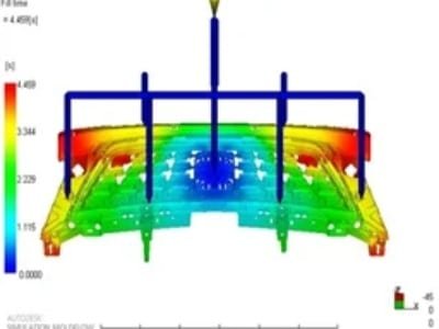
Here is a video that shows how injection molding weld line develop. Watching it would provide a more intuitive understanding of the formation of welding lines.
What Causes Weld Lines In Injection Molding?
Temperature
Temperature differentials in the molten plastic material can contribute to the formation of weld lines. Significant differences in temperature between flow fronts can result in poor fusion when they meet, leading to a visible injection molding weld line.
Incorrect Injection Pressure
Improper injection pressure settings can disrupt the flow of the molten plastic material and cause the flow fronts to split and rejoin, resulting in weld lines. Insufficient or excessive injection pressure can both contribute to weld line formation.
Low Injection Speed
Slow injection speeds can increase the chances of injection molding weld line occurrence. Insufficient speed can allow the material to cool and solidify before the flow fronts converge, resulting in poor fusion and visible weld lines.
Impurity
The presence of impurities or contaminants in the plastic material can lead to the formation of weld lines. These impurities can act as nucleation sites for premature solidification and hinder proper fusion between flow fronts.
Mold Design
The design of the mold can influence the occurrence of the injection molding weld line. Factors such as gate placement, mold complexity, and venting play a role in controlling the flow of the molten plastic and minimizing the formation of weld lines.
Excess Mold Release
The excessive use of mold release agents or improper application can create a thin layer on the mold surface, which may interfere with the fusion of flow fronts and contribute to injection molding weld line formation.
How To Solve Weld Line In Injection Molding?
How to reduce the weld line in injection molding, there are several approaches that can be taken:
Injection Molded Part Design
Increasing wall thickness helps improve pressure transmission and maintain a higher melt temperature, slowing the cooling rate and allowing more time for the resin to flow and fuse.
Avoid excessive thickness to prevent sink marks. Reducing the wall thickness ratio improves flow, enabling the melt to cover a wider area faster, which helps close weld lines.
Adjusting gate size and position to keep weld line areas away from part edges can reduce the risk of breakage.

Injection Mold Design
Adjusting gate location can redirect material flow and position weld lines in less visible or less critical areas.
Choosing a hot runner system over a cold runner offers better thermal control, keeping the plastic molten longer and improving flow consistency.
Additionally, proper venting is essential to prevent trapped air, which can hinder flow and weaken weld lines.

Injection Molding Process
Two critical processing factors influence weld lines in injection molding: melt and mold temperature, and injection speed and pressure.
Maintaining higher melt and mold temperatures helps ensure the molten fronts fuse more completely, reducing weld line formation. However, temperatures must stay within the material supplier’s recommended range to prevent plastic degradation. Increasing injection speed and pressure can keep the melt fronts hotter by filling the cavity faster, which shortens weld line length and promotes better fusion.
Material Selection
When mold or design changes aren’t possible, improving weld lines relies on material optimization. Increasing flowability by reducing powders or additives, avoiding paint-required materials for parts with holes, and adding heat stabilizers for heat-sensitive plastics help enhance weld line strength and appearance.

What is the Difference Between Weld Line and Meld Line?
Weld lines and meld lines are all terms used in the context of injection molding to describe specific types of surface defects that occur during the molding process. While they are related, there are slight differences between them:

Weld lines are visible lines or seams formed when molten plastic flow fronts meet and fuse together, often due to obstacles or flow interruptions in the mold.
Meld lines occur when flow fronts meet and fuse without interruptions, typically around geometric features or thin sections of the mold.
Conclusion With Weld Lines In Plastic
In conclusion, injection molding weld lines, knit lines, and meld lines are common surface defects in injection molding. While they may impact the appearance and strength of the molded parts, understanding their formation allows for effective mold design and process optimization to minimize their occurrence. Zhongde is an injection molding manufacturer helping you achieve high-quality parts with excellent appearance and functionality.