Modern product designs increasingly include complex geometries, angled surfaces, and tight tolerance requirements that push beyond what conventional machining setups can efficiently deliver. In many cases, this leads to design compromises or additional production steps that slow down the overall development cycle.
To overcome these challenges, modern CNC technology has evolved toward more flexible machining approaches that reduce setups and improve accessibility to complex geometries. One of the most important of these solutions is multi-axis machining. But how exactly does it enable this level of manufacturing capability?
What Is Multi-Axis Machining?
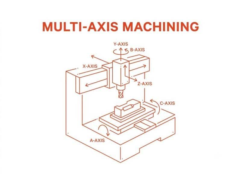
An axis is simply a direction the cutting tool or workpiece can move along or rotate around. Standard CNC milling uses three linear axes — X, Y, and Z. Multi-axis machining adds rotary axes (A, B, or C) that tilt or rotate the tool or workpiece, allowing the machine to approach the part from multiple directions and machine complex geometry with fewer setups.
How Does Multi-Axis Machining Work?
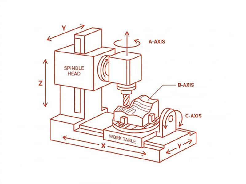
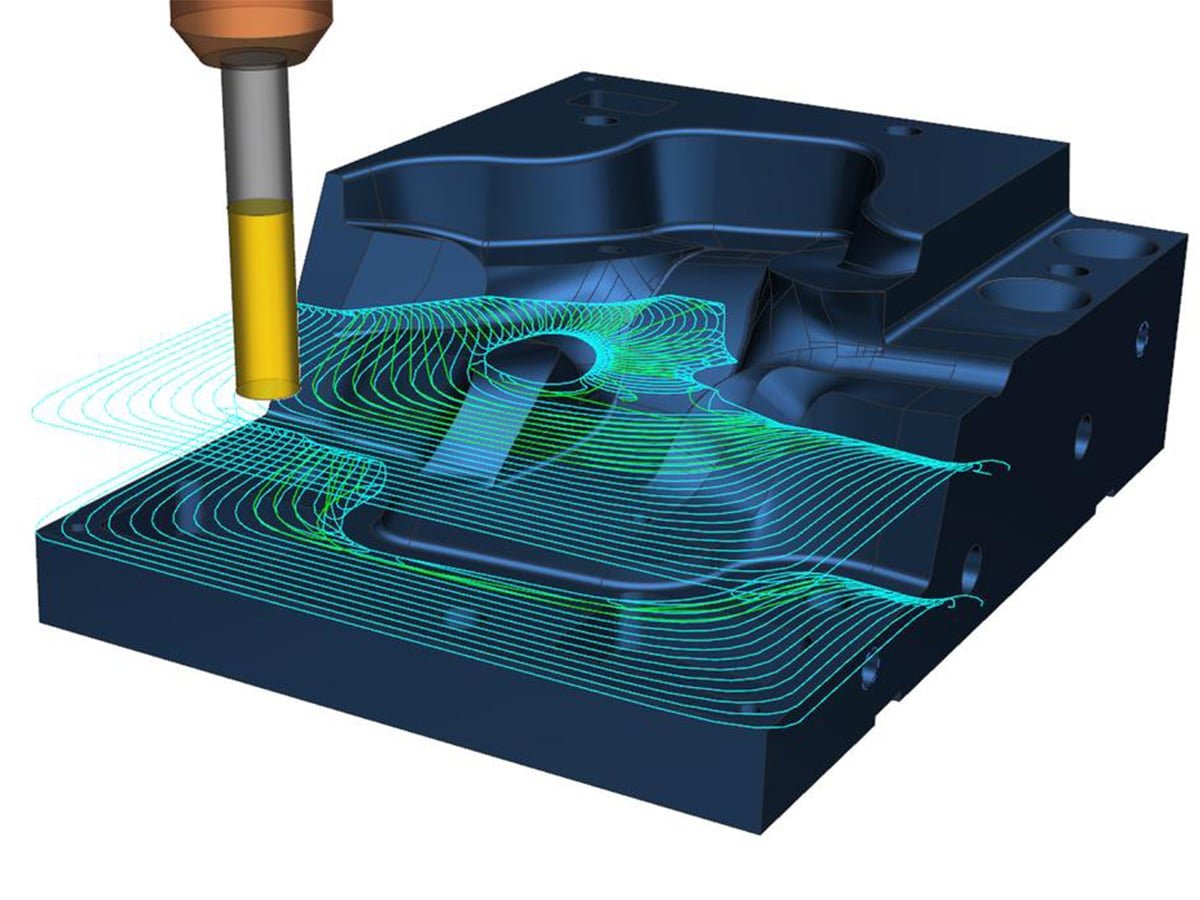
A CAM program calculates the toolpath from the part’s CAD model, and the machine controller coordinates the axes to follow that toolpath. During machining, the rotary axes can reposition or continuously adjust the part or tool head, keeping the cutting edge at a suitable angle as it moves across curved or angled surfaces.
By reducing the need to reposition the workpiece between operations, multi-axis machining can keep features referenced to the same setup, reducing alignment errors between them.
Configurations of Multi-Axis Machining
Machine shops choose between several standard configurations depending on part complexity and production volume. Here’s a quick look at what each one adds. For a more detailed comparison of capabilities, accuracy, setup requirements, and typical applications, see our 3-Axis vs. 4-Axis vs. 5-Axis CNC Machining guide.
3-Axis
The baseline configuration, moving the tool along X, Y, and Z only. Well suited to flat or simple contoured parts that don’t require access from multiple angles.
4-Axis
Adds a single rotary axis (typically A), letting the part rotate to access additional sides without manual repositioning. Common for parts with features around a cylindrical surface.
5-Axis
Adds a second rotary axis, allowing the tool or table to tilt as well as rotate for access to complex surfaces and features. It is well suited to complex, high-precision geometry that requires multiple tool orientations.
Beyond 5-Axis
Some platforms add further rotary or linear travel — for example, a rotary table plus a tilting head, or multiple spindles working in tandem. These configurations target very large parts, multi-part production, or workflows that combine machining with secondary operations like grinding or inspection in a single cell.
Terms like 9-axis do appear in the industry, but at that point the count usually includes axes from a secondary spindle, sub-turret, or live tooling working alongside the main milling axes, rather than following the same single-toolpath logic as 3, 4, and 5-axis machines.
Advanced Technologies in Multi-Axis CNC Machining
Multi-axis CNC machining has moved well beyond simple 3-axis milling. Modern production combines simultaneous multi-axis motion, real-time sensing, and adaptive control to maintain tight tolerances on complex geometries at production speeds.
Adaptive Toolpath Control
Adaptive control systems monitor spindle load, vibration, and cutting force in real time, then adjust feed rate and cutting parameters as needed. This keeps the tool within a suitable cutting range as material hardness or wall thickness varies, helping extend tool life and reduce chatter or deflection on delicate features.
In-Process Probing and Metrology
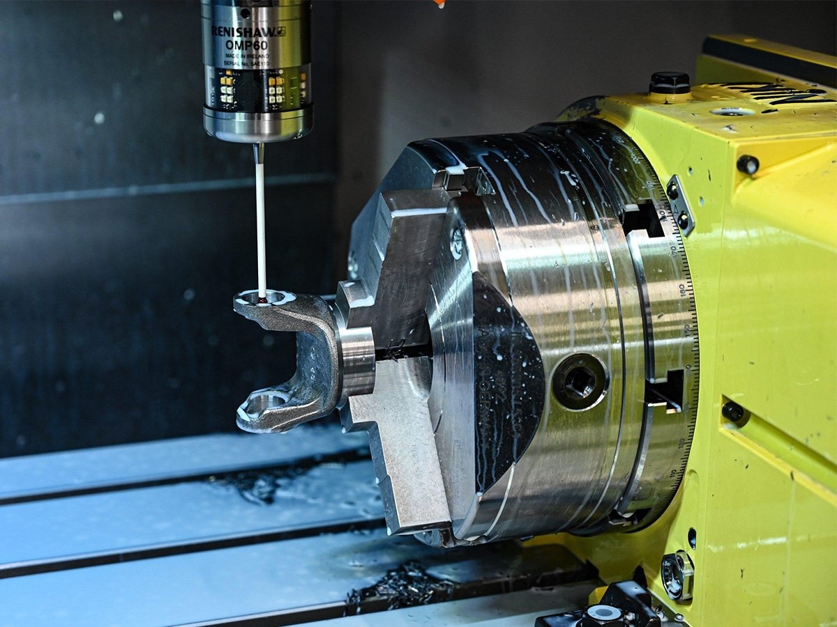
Touch probes and laser measurement systems mounted on the machine check part position, tool wear, and dimensional accuracy between operations. Measurements can feed back into the control system to update offsets automatically, reducing setup errors and limiting the need for separate inspection of selected features.
High-Speed Machining (HSM) Strategies
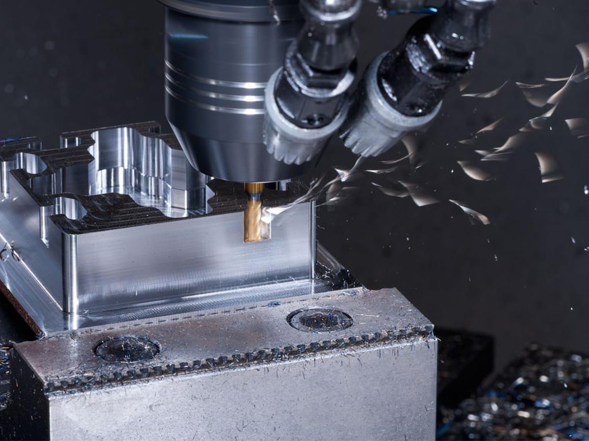
HSM combines high spindle speeds with optimized toolpaths — including trochoidal milling, constant chip-load control, and smooth entry and exit moves — to remove material efficiently while reducing tool stress. These strategies can shorten cycle times and improve surface finish when machining materials such as hardened steels, aluminum, and engineering plastics.
Automated Workholding and Robotic Loading
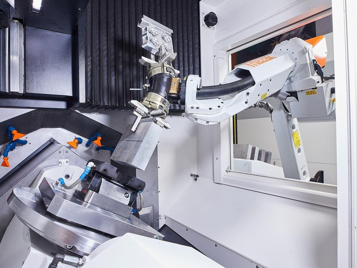
Zero-point clamping systems and robotic part loading allow multi-axis machines to run with less operator intervention across shift changes. Repeatable workholding helps maintain consistent part positioning, supporting automated and lights-out production where the process is suitable.
Data-Driven Process Monitoring
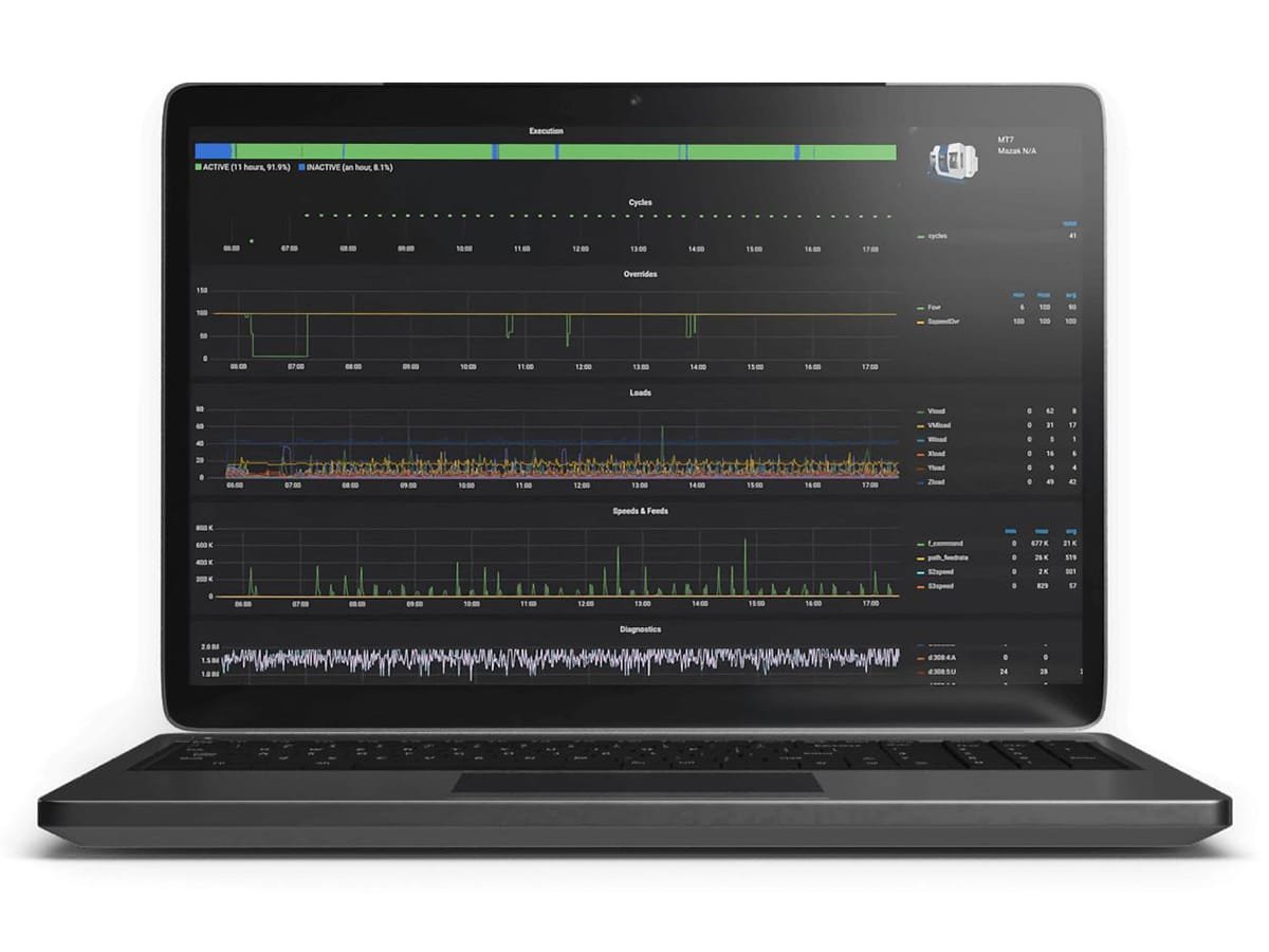
Machine-mounted sensors and shop-floor connectivity capture spindle load, temperature, and vibration data during production. Over time, this data can reveal tool wear trends and process drift before they lead to defects, supporting predictive maintenance and consistent part quality during longer production runs.