Wall thickness is often treated as a secondary detail in early design—but in injection molding, it is usually one of the first parameters that quietly decides whether a part is easy to produce or difficult to control.
The sections below break down how thickness behaves in real molding conditions, and how small design choices can lead to very different manufacturing outcomes.
What is Injection Molding Wall Thickness?
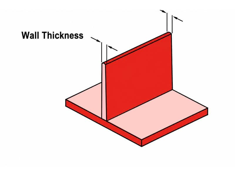
Injection molding wall thickness refers to the distance between the two opposite surfaces of a molded plastic part. It is a fundamental geometric parameter that determines how the material fills, cools, and solidifies inside the mold cavity. In practical design, wall thickness is typically defined as a nominal value with controlled variation across the part geometry.
Minimum and Maximum Wall Thickness
The minimum wall thickness is the thinnest section that can be reliably filled during injection molding. It is primarily limited by material flowability, part size, and injection pressure. If the wall is too thin, the melt may freeze prematurely, leading to short shots or incomplete filling.
The maximum wall thickness is the thickest section that can be used without causing significant defects such as sink marks, internal voids, or excessive cycle time. Thick regions cool more slowly, which creates uneven shrinkage and increases internal stress.
In practice, successful designs aim to keep wall thickness as uniform as possible, staying within a controlled range defined by both material behavior and part function.
Why Injection Molding Wall Thickness Matters
Wall thickness is one of the most critical design parameters in injection molding. It influences almost every stage of the process—from how material flows into the cavity to how the final part performs in real-world use.
Material Flow Behavior Control
Wall thickness determines how molten plastic travels through the mold cavity. If the thickness is uneven, the melt front will slow down or accelerate unpredictably, leading to flow imbalance, short shots, or weld lines in critical areas.
Cooling Time and Production Efficiency
Thicker walls require significantly longer cooling time because heat must dissipate through a greater mass of material. This directly increases cycle time, reducing overall production efficiency and raising unit cost.
Part Shrinkage and Dimensional Stability
Non-uniform wall thickness causes uneven shrinkage during cooling. This often leads to warpage, sink marks, or internal stress, all of which reduce dimensional accuracy and long-term stability.
Structural Strength and Failure Behavior
Wall thickness is not simply about making a part “stronger.” Improper thickness distribution can create stress concentration zones, which may actually weaken the part under load or impact.
Design Freedom and Manufacturability
Injection molding design is constrained by what can be filled, cooled, and ejected reliably. Proper wall thickness design enables more complex geometries without risking defects or moldability issues.
Design Guidelines for Injection Molding Wall Thickness
In practical design work, wall thickness should be defined early and controlled consistently throughout the part. Most molding issues can be traced back to inconsistent or poorly managed thickness distribution, so decisions here should be made with manufacturability in mind, not just geometry.
You can also learn more about plastic parts design in our guide on A Practical Guide to Injection Molding Design and Manufacturability.
Establish a Nominal Wall First
For most general-purpose thermoplastics, start with a nominal wall thickness of 1.5–3.0 mm as a baseline. Engineering plastics may require adjustment within 1.0–4.0 mm depending on flowability and structural demand. Once selected, this value should remain consistent across the main body of the part unless functionally justified.
Avoid Sudden Thickness Changes
Local thickness changes should generally stay within ±25% of the nominal wall. For example, a 2.0 mm wall should not suddenly expand beyond 2.5 mm or drop below 1.5 mm without transition. Larger jumps should be redesigned with gradual blending or coring.
Control Rib and Boss Proportions
Rib thickness is typically designed at 50–70% of the nominal wall to balance strength and surface quality. Boss walls should also avoid exceeding the surrounding wall thickness. Excess material accumulation in these features often leads to visible sink and longer cooling time.
Consider Flow Direction During Layout
Wall thickness should remain stable along the main flow path. Sudden expansion of flow cross-section should be avoided, as it can cause hesitation, weld lines, or incomplete filling in downstream areas.
Validate with Simulation Before Tooling
Before mold release, run flow and cooling simulation to verify that thickness distribution does not create excessive cooling time differences. Areas with significantly longer cooling cycles often indicate local over-thick regions that should be optimized before steel is cut.
How Material Shrinkage Affects Wall Thickness Design
Material shrinkage is one of the key reasons wall thickness must be carefully controlled in injection molding. As molten polymer cools, it contracts at different rates depending on material type, wall thickness, and cooling conditions. If thickness is not designed properly, shrinkage becomes uneven, leading to warpage, sink marks, or dimensional drift.
Thicker sections cool more slowly and continue shrinking after thinner areas have already stabilized. This imbalance creates internal stress and often pulls the part out of tolerance. Therefore, wall thickness design must always be considered together with the shrinkage behavior of the selected material.
Below is a reference overview of common injection molding material and their typical recommended wall thickness ranges.