Injection molding parts often look perfect in CAD, but behave differently once they meet a real mold. One of the most common surprises happens when a part refuses to release smoothly from the cavity.
At first glance, it usually feels like a tooling issue or a processing problem. But in many cases, the cause is much simpler—and it comes down to how the walls of the part are angled.
So why does a tiny angle make such a big difference in demolding behavior? And how much is actually needed to avoid problems?
What Is a Draft Angle?
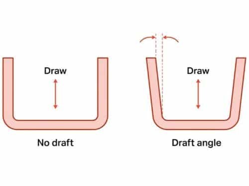
A draft angle is a small intentional slope added to the vertical walls of a molded part, so the part can be removed from the mold more easily.
In simple terms, instead of a wall being perfectly straight, it is slightly angled—wider at the top and a bit narrower toward the base (or vice versa depending on the mold direction). This tiny geometric adjustment reduces friction between the plastic part and the steel cavity during ejection.
Why Draft Angle Matters in Injection Molding?
Understanding what draft angle is is only the first step. The real question in production is simple: what actually goes wrong if a part has too little draft—or none at all?
Part Ejection Ease
When molten plastic cools, it shrinks and wraps tightly around the steel surface of the mold. If the wall is perfectly vertical, it behaves a bit like a suction cup on glass—hard to pull away.
A small draft angle breaks that “vacuum-like grip”, allowing the part to release smoothly instead of resisting the mold opening.
Surface Quality Control
Without draft, the part is forced to scrape along the steel wall during ejection. This is similar to dragging a plastic box across a rough table—tiny scratches or shiny drag marks can appear. In molded parts, these defects are often permanent and visible on final products.
Dimensional Stability
During ejection, a poorly drafted part may flex, warp, or get temporarily deformed as it is forced out of the mold. This can lead to inconsistent dimensions, especially in thin-walled or tall features. Draft helps the part exit with less stress, allowing it to retain its intended shape more reliably.
Cycle Time Efficiency
When parts release easily, the mold opens and closes without hesitation. If parts stick even slightly, operators or machines may need extra time, force, or adjustments. Over thousands of cycles, those small delays add up to significant production loss. Draft angle helps keep the process consistent and predictable.
Tool Life Extension
A mold is not cheap, and it is expected to run thousands or even millions of cycles. No draft means more scraping, more wear, and more long-term damage to polished cavity surfaces. With proper draft, contact is lighter and more uniform, which reduces tooling wear over time.
Factors That Affect Draft Angle Design
In real tooling, draft angle is never chosen as a single fixed number. It changes depending on how the part is shaped, how it is used, and how it interacts with the mold during cooling and ejection.
Part Depth
A shallow part is easy to release, almost like lifting a coin straight out of a tray. But once the cavity becomes deeper, the contact area between plastic and steel increases significantly. The deeper the wall, the more “grip” builds up during cooling, which means a larger draft is usually needed to avoid that suction-like resistance.
Surface Texture
Smooth steel surfaces allow plastic to slide more easily. But when textures are added—like matte finishes or leather grain—the surface behaves more like sandpaper in reverse. Instead of sliding, the part tends to hold onto the mold wall more tightly, so additional draft is often required to compensate for this increased friction.
Material Shrinkage
Different plastics shrink at different rates as they cool. Some materials pull away cleanly from the mold wall, while others cling more tightly as they contract. It’s similar to how a rubber object behaves differently from a rigid plastic when stretched and released—the internal stress changes how easily it detaches.
Tooling and Ejection Method
Not all molds release parts the same way. Some rely heavily on ejector pins, while others use stripper plates or angled shutoffs. When ejection force is concentrated in a few points, designers often increase draft to reduce localized stress. In more balanced ejection systems, slightly lower draft may still work without quality issues.
Design Guidelines for Draft Angle
If the previous section felt a bit theoretical, this is where things become practical. In real design work, engineers rarely calculate draft angles from scratch every time. Instead, they rely on a set of practical rules that work well in most production conditions and then fine-tune them when needed.
Define Draft Direction First
Always set the draft angle relative to the mold opening direction, not the part geometry itself. In most cases, this is the Z-axis in CAD aligned with ejection direction. In practice, you should imagine the part being pulled straight out of the mold—every vertical face should slightly open up along that path, not lean against it. A correct draft always reduces contact during extraction rather than increasing it.
Use 1–2° as Baseline
Most injection molded parts use a draft angle between 1° and 2° per side as a standard starting point. This range is usually enough for shallow walls and general-purpose plastic parts where surface finish is not highly sensitive. If you are unsure where to begin, this is the default safe zone for most designs.
Add 0.5° per 25 mm Depth
For deeper walls, increase draft as height increases. A practical rule is +0.5° draft per 25 mm of wall depth per side. For example, a 50 mm wall typically needs around 1.5°–2°, while a 75 mm wall often performs better at 2° or slightly above. This keeps ejection force stable along the full surface.
Increase 1°–3° for Textured Surfaces
Surface texture significantly increases mold grip. Light texture usually requires 2° per side, while medium to heavy textures often need 3°–5° per side. As a rule, assume that any visible texture adds at least +1° compared to a smooth surface.
Apply 0.25°–0.5° Extra for Deep Ribs and Bosses
For narrow ribs, bosses, or tall cylindrical features, add an additional 0.25°–0.5° per side beyond normal wall requirements. These features trap friction more easily because contact happens on multiple surrounding faces, not just one wall.
Adjust for Material Shrinkage
Materials with higher shrinkage or filler content (such as glass-filled nylon or PC+GF) tend to grip mold walls more strongly after cooling. In these cases, it is common to increase draft by an additional 0.5°–1° per side compared to standard ABS or PP parts, even if the geometry is unchanged.
Reduce Only When Function Requires It
When a surface is sealing, guiding, or cosmetic-critical, draft can be reduced—but rarely removed. In practice, designers usually keep at least 0.5° per side as a minimum safety angle, even on functional surfaces. Anything lower than this tends to create visible drag or requires special mold polishing or side-action compensation later in tooling.
Conclusion
Draft angle may look like a small detail, but as we’ve seen, it directly affects part release, surface quality, tool wear, and overall production stability.
If you want more practical guidance on part development, you can explore our Injection Molding Design guidance, or learn how we support projects through our Custom Mold and Tooling Service. For direct project support, feel free to contact Zhongde for practical engineering feedback and manufacturing solutions.