Some molded parts have several defects such as flash, dimensional inaccuracies, or even premature mold damage, that all related to an injection molding parameter, it is the injection molding clamping force.
What Is Injection Molding Clamping Force?
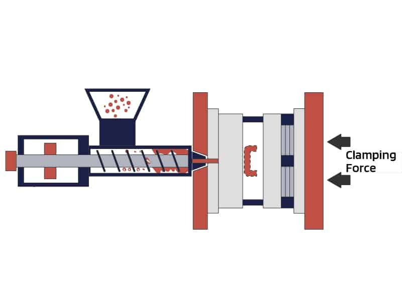
Injection molding clamping force is the force exerted by the clamping unit of the injection molding machine to hold the two halves of the mold together during the injection and packing phases. It counters the pressure generated by the molten plastic inside the mold cavities and runners. The unit is typically expressed in tons or kilonewtons (kN). It is applied during the injection and packing phases.
The required clamping force depends on the internal cavity pressure, which arises from the injection speed, material viscosity, and part geometry. In custom injection molding, the clamping force must match the specific project requirements to maintain consistent mold closure without unnecessary energy use.
Why Proper Clamping Force Matters in Injection Molding
Impact on Part Quality and Mold Closure
Clamping force in injection molding maintains mold closure to prevent the separation of mold halves under high internal pressure. This directly supports part quality by ensuring dimensional accuracy and surface finish.
Risks of Insufficient Clamping Force
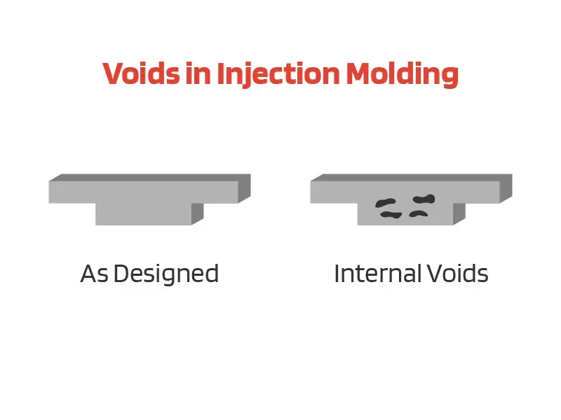
When the clamping force is too low, the mold may open slightly during injection or packing. This results in flash, where excess plastic escapes along the parting line. It can also cause short shots, uneven wall thickness, or inconsistent part weights. These issues increase scrap rates and require additional trimming or rework.
Risks of Excessive Clamping Force
Excessive clamping force creates different challenges. It can compress the mold too tightly, restricting air vents and leading to trapped gases that cause burn marks or surface defects. Over time, high force accelerates wear on the mold parting lines, tie bars, and platens. It also raises energy consumption and may reduce machine lifespan.
Clamping Force Calculation Methods
Clamping force calculation is a core step in mold design and machine selection. Three main methods are used: empirical formulas for quick estimates, precise pressure-based calculations, and production-based optimization for fine-tuning.
Empirical Formula (Quick Estimation)
The empirical approach uses a material-specific constant (Kp) multiplied by the projected area of the part and runners. The formula is:
F=Kp×S
where F is the clamping force in tons, Kp is the material constant in tons per cm², and S is the projected area in cm². A safety factor of 10–20 percent is typically added before selecting the machine tonnage.
Precise Formula (Recommended for Accuracy)
The more accurate method accounts for actual cavity pressure:
F=P×S×K
where F is clamping force in tons, P is average cavity pressure (typically 300–800 bar depending on material and flow length), S is projected area in cm², and K is the safety factor (1.1–1.3). Unit conversion is required: cavity pressure in bar multiplied by area in cm² gives force in appropriate units, then divided by 1000 for metric tons after adjustment.
Steps:
- Calculate the projected area on the parting line (2D view of cavities and runners).
- Determine cavity pressure from material data sheets or simulation, considering wall thickness, flow path, and viscosity.
- Apply the safety factor.
Production Optimization (Weight Method)
The most reliable approach involves running trials on the actual machine. Start at 90 percent of maximum clamping force, then reduce in increments of 5–10 tons while monitoring part weight and appearance. The optimal point is where part weight stabilizes without flash. This method, often called the RJG weight method, accounts for real process conditions and material behavior.
Key Factors Affecting Clamping Force
Several variables influence the required injection molding clamping force.
Material Properties
Material properties are primary. Higher-viscosity materials such as PC or glass-filled PA generate greater cavity pressure and need a higher force. Thin walls or long flow paths also increase pressure requirements.
Part Design
Part design plays a significant role. Multi-cavity molds raise the total projected area. Complex shapes with deep cores or varying wall thicknesses affect pressure distribution. Runners and gates contribute to the total area and must be included in calculations.
Mold Design
Mold and process parameters matter as well. Gate location, venting design, melt temperature, and injection speed all affect cavity pressure. Machines with toggle mechanisms may provide more uniform force distribution than hydraulic types in some applications.
Projected Area
Projected area is the most influential factor. Larger parts or multi-cavity molds require significantly higher clamping force due to the increased surface area exposed to cavity pressure.
Common Problems Related to Clamping Force
Flash
Insufficient clamping force often produces flash along the parting line. The cause is usually under-calculation of projected area or cavity pressure, or machine settings below the required level. The solution involves increasing force in controlled steps and verifying with part inspection and weight checks.
Burn Marks and Short Shots
Excessive clamping force leads to poor venting, resulting in burn marks or short shots, especially in thin sections. It can also damage the mold or tie bars over time. The remedy is to reduce force to the minimum stable level identified through weight trials and to ensure proper venting design.
Other Problems
Other issues include uneven tie-bar loading, which causes mold wear or inconsistent parts. Regular monitoring with strain gauges or sensors helps maintain balance. Long-term operation at maximum force accelerates equipment fatigue. Best practice is to operate at 70–80 percent of machine capacity when possible.
How Zhongde Ensures Proper Clamping Force
Calculating the clamping force is a challenge to apply and control throughout the entire manufacturing process. We integrate clamping force optimization into every stage of production:
- Engineering Evaluation: Our team calculates injection molding clamping force based on part geometry, material selection, and production requirements.
- Mold Design Expertise: We design molds to reduce unnecessary projected area and improve flow efficiency, minimizing required tonnage.
- Advanced Simulation: Moldflow analysis is used to predict cavity pressure and validate clamping force before tooling is finalized.
- Flexible Machine Capacity: We operate a wide range of injection molding machines, allowing precise matching between product requirements and machine tonnage.
- Custom Production Capability: From low-volume prototyping to high-volume manufacturing, we maintain consistent process control and quality output.
Conclusion
Working with an experienced manufacturing partner can significantly reduce risk and improve outcomes. With strong engineering support, optimized mold design, and flexible production capabilities, it is possible to ensure that the clamping force is precisely controlled at every stage. If you are looking to improve part quality or optimize your injection molding process, partnering with Zhongde can provide a reliable and efficient solution.