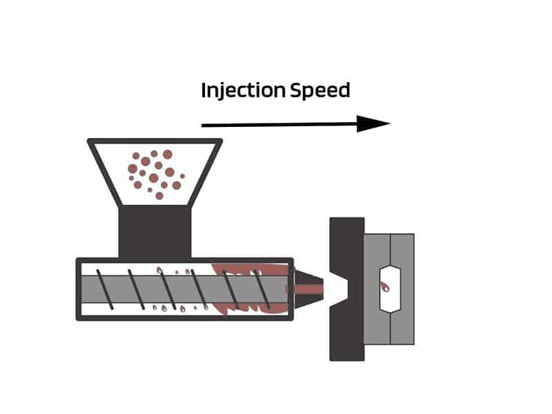
Injection speed is one of the most critical parameters in the injection molding process. It determines how quickly molten plastic enters the mold cavity and directly affects part quality, cycle time, and production efficiency. A proper understanding of injection speed is important to optimize the injection molding process and minimize defects.
What is Injection Speed?
Injection speed is the rate at which the molten polymer is injected into the mold cavity. It is typically expressed in units such as cubic centimeters per second (cm³/s) or millimeters per second (mm/s). Some injection molding machines also measure speed in terms of screw velocity, depending on the system configuration.
Why is Injection Speed Important?
Injection speed governs several aspects of the molding outcome. It controls how quickly the melt front advances, which affects shear heating, molecular orientation, weld-line formation, surface finish, and dimensional stability. Proper speed ensures the cavity fills completely before significant cooling occurs at the walls, reducing risks of short shots or sink marks. It also influences cycle time: faster filling shortens the injection phase, allowing higher output.
Speed impacts shear rate near the gate and along flow paths. Higher speeds generate more frictional heat, which can lower viscosity temporarily and improve flow in thin sections. Lower speeds reduce shear stress, limiting molecular alignment that might cause warpage or weakness. In practice, speed affects nearly every visible and structural characteristic of the part, often more than adjustments to temperature or hold pressure alone.
How to Calculate Injection Speed?
The basic calculation for injection speed uses a simple relationship:
Injection speed = Shot volume ÷ Injection time
For example, if a mold requires 50 cm³ of molten plastic and the injection time is 2 seconds, the average injection speed is 25 cm³/s. However, this calculation serves only as a starting point. In practice, engineers must account for factors such as material viscosity, wall thickness, mold temperature, and part geometry. Adjustments may also be required during trial runs or simulations to achieve the desired results.
High and Low Injection Speed
Injection speed can be categorized as high or low, with distinct effects on the molding process:
High Injection Speed
High injection speed offers clear advantages in certain situations.
- It shortens fill time, which reduces cycle length and increases productivity.
- Suitable for thin-walled parts, the fast filling overcomes rapid cooling at the walls, preventing freeze-off before the cavity completes.
- Surfaces often appear glossier, weld lines form more strongly due to retained heat at merge points, and overall deformation decreases from more uniform packing.
However, high speed carries risks.
- Excessive shear can degrade sensitive resins, producing burn marks from trapped air overheating.
- Jetting appears as snake-like patterns when molten material shoots into open areas at high velocity.
- Flash occurs if pressure spikes push material beyond the parting line.
- Air entrapment becomes more likely without proper venting.
Low Injection Speed
Low injection speed provides gentler filling.
- It reduces turbulence, limiting jetting, flow marks, and burn defects.
- Flash risk drops because the final pressure buildup stays controlled. Dimensional accuracy improves from even cooling and lower internal stresses.
- Molecular orientation remains minimal, which helps avoid warpage in parts prone to shrinkage differences.
Low injection speed will cause some other issues.
- Longer fill times, which extend cycles and lower output.
- Premature solidification causes short shots, especially in thin or long-flow sections.
- Sink marks appear more readily in thick areas due to insufficient packing pressure before freeze-off.
- Weld lines weaken from cooler melt at meeting points.
Single-stage high or low speed rarely suits complex parts. Modern machines support multi-stage injection speed that combines benefits while minimizing drawbacks.
Concept of Multi-Stage Injection Speed
Multi-stage injection speed is a technique in which the injection process is divided into several phases with different speeds. Cavity resistance changes continuously during filling. Wide runners offer low resistance at first, narrow gates create sudden restriction, and varying wall thicknesses alter flow further. A constant screw speed produces uneven melt-front velocity, leading to hesitation marks, orientation stress, or defects.
Multi-stage injection divides the screw stroke into segments, each with its own speed setting. Typically, the initial stage begins at a slower speed to reduce the risk of jetting, followed by a faster mid-fill stage to quickly fill the bulk of the cavity, and a slower packing stage to minimize internal stresses.
Principles for Setting Reasonable Injection Speeds
Setting injection speed follows several guiding rules derived from flow behavior and practical experience.
First, the principle of injection speed is to target a consistent melt-front velocity across the cavity. Variable cross-sections mean volumetric flow rate must change to keep front speed steady, reducing flow marks and internal stress.
Second, fill runners and manifolds at a higher speed. This shortens overall cycle time and prevents premature cooling in feed systems.
Third, reduce speed at or near the gate. Slow entry avoids jetting, gate blush, or splay, particularly with amorphous materials like PC, PMMA, or ABS through side or pinpoint gates.
Fourth, accelerate in the main cavity after the gate. Moderate to high speed improves gloss, strengthens weld lines, and ensures complete filling before wall solidification advances too far.
Fifth, decelerate sharply in the final 10–15% of fill. Low speed controls pressure rise, prevents flash, and protects the mold from excessive force.
Sixth, match the speed profile to part geometry and material. Thin, long paths need higher overall speeds; thick sections benefit from slow-fast-slow patterns to avoid sink or voids. Crystalline resins like PP or PA tolerate faster filling; amorphous types require more caution to preserve clarity.
Seventh, use short-shot progressive fills and cavity pressure curves for refinement. Start with low uniform speed, increase incrementally, assign stages based on appearance, and fine-tune transition positions.
Eighth, coordinate speed with other parameters. Higher speed often requires a corresponding pressure increase to overcome resistance; slower speeds allow lower pressure but demand careful hold time to pack adequately.
The Influence of Mold Geometry on Injection Speed Setting
Mold geometry dictates resistance changes, making injection speed adjustments for uniform filling.
- Thin-walled sections demand higher speeds to complete filling before freeze-off locks flow paths.
- Thick walls or ribs require slower initial entry followed by acceleration, then deceleration to prevent sink marks or internal voids from uneven packing.
- Long flow lengths benefit from high early speed to minimize cooling distance.
- Sudden cross-sectional increases (e.g., from gate to cavity) need deceleration before the expansion to avoid hesitation or flow instability.
- Multiple or radial gates call for balanced acceleration to ensure even arrival at weld points.
- Small gates or restrictive features require a slow approach to limit shear damage, followed by resumption of speed.
- Complex details with varying thickness often need segmented profiles—high in open areas, low near restrictions—to achieve consistent density and minimal shrinkage variation.
Improving Product Defects through Injection Speed
Many common defects respond directly to speed adjustments.
- Short shots occur when the melt solidifies before reaching the extremities. Increase speed in early or mid stages to improve flow before freeze-off advances.
- Flash results from excessive material pushed beyond the parting line. Reduce final-stage speed sharply to control pressure buildup at 90–95% fill.
- Jetting produces visible snake-like traces on the surface. Slow speed at gate entry while keeping runner fill rapid; this allows controlled expansion into the cavity.
- Splay or silver streaks arise from flow instability or moisture/gases. Smooth transitions across stages, especially in glass-filled materials, reduce abrupt shear changes.
- Sink marks appear in thick areas from insufficient packing. Raise mid-stage speed to retain heat and improve material compressibility during hold.
- Weld-line weakness stems from the cool melt meeting. A faster approach to merging points preserves temperature and increases bonding strength.
- Burn marks form from compressed trapped air. Lower overall speed or improve venting; high speed exacerbates overheating in dead zones.
- Flow marks or hesitation lines indicate uneven front advance. Adjust stages for nearer-constant velocity, eliminating pauses at thickness changes.
Conclusion
Injection speed is not a single fixed value but a dynamic profile tailored to material, mold geometry, and quality targets. Multi-stage control allows precise management of filling behavior, balancing fast cycles with defect-free parts. When set reasonably, injection speed enhances surface finish, dimensional accuracy, internal integrity, and production efficiency. Zhongde provides professional injection molding services with an experienced team. Welcome to contact us and get a high-quality molding service.