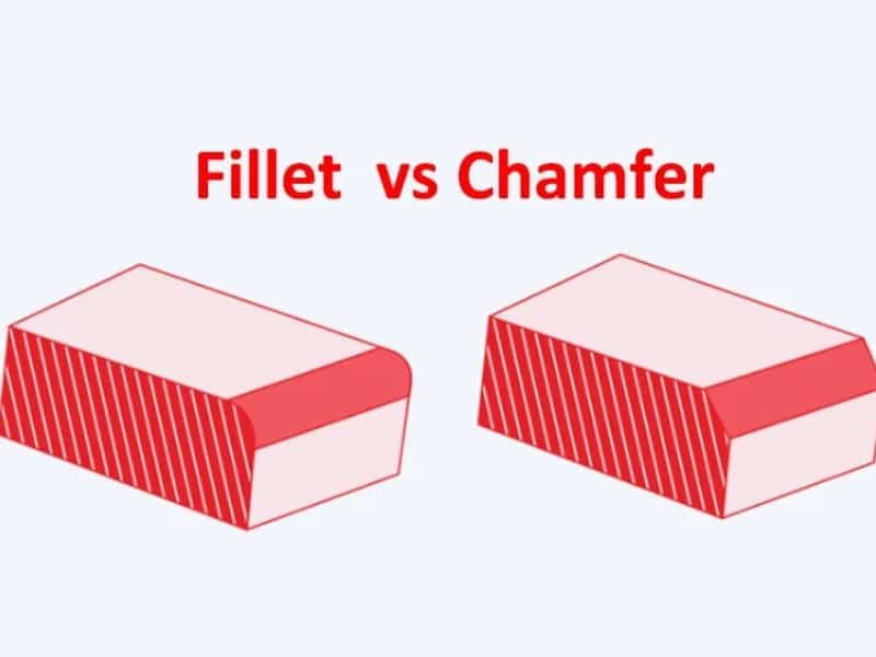
In injection molding, corners are one of the most sensitive features in a plastic part design. Sharp edges can lead to stress concentration, poor flow during filling, and higher risk of cracking or warping. In contrast, well-designed radiused corners help the material flow more smoothly into the cavity, improve structural strength, and reduce mold wear over time.
In this article, we will look at how to properly design corners for plastic injection-molded parts, and what practical guidelines can help you balance strength, appearance, and manufacturability.
What are Sharp Corners?
A sharp corner is a sharp, shallow angle in a part or mold, typically occurring at junctions or within cavities. While designed to achieve precise geometry and positioning, sharp corners can become stress concentration points during manufacturing and use, potentially leading to material cracking or mold wear. Therefore, sharp corners are often rounded or chamfered to improve flow, reduce stress, facilitate demolding, and increase overall part strength and life.
Plastic Part Corner Design Principles
When designing plastic parts, sharp corners, right angles, or notches should be avoided at the junctions between walls, along the flow path of the molten plastic, and at the connections between walls and ribs, snaps, or posts. These features should be replaced with fillets, following the fillet design principles for plastic parts.
Fillets are designed to prevent stress concentration at sharp corners. Due to variations in the shape and cross-section of plastic parts, the flow of molten plastic changes abruptly at sharp corners during injection molding, generating high stresses that tend to remain in these areas.


Stress concentration is a major cause of failure in plastic parts under load. The stress distribution at sharp corners and fillets is shown in the figure below. Doesn’t it look like it could break easily?

How to Design Correct Corner Radii
When designing corner radii for injection-molded parts, the goal is to improve flow, reduce stress concentration, and avoid unnecessary tooling complexity. Below are practical, engineering-focused tips you can apply directly in design work:
- Avoid sharp internal corners (0 radius is not acceptable). Always replace sharp 90° internal corners with a fillet. A zero-radius corner creates stress concentration, restricts melt flow, and increases the risk of cracking and short shots.
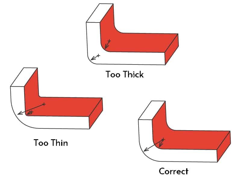
- Use a consistent radius-to-wall-thickness ratio. A common rule is: Internal radius = 0.5 × to 1.0 × wall thickness. This helps maintain uniform flow and reduces pressure buildup during filling.
- Match internal and external radii properly. When adding internal fillets, ensure the outer corner is adjusted accordingly to maintain uniform wall thickness. Uneven thickness can lead to sink marks or warping.
- Prioritize larger radii in high-stress areas. For load-bearing or impact-prone regions, use a larger radius (closer to or slightly above wall thickness). This improves fatigue resistance and reduces crack initiation risk.
- Keep radii consistent within the same part when possible. Avoid frequent changes in corner radius size. Consistency improves mold filling balance and reduces flow hesitation marks.
- Consider tool machining limitations. Extremely small radii can be difficult or expensive to machine in steel molds. Wherever possible, design radii that are compatible with standard end mills to reduce tooling cost.
- Balance aesthetics and function in visible areas. For consumer-facing parts, slightly larger radii often improve both appearance and perceived quality, while still maintaining structural performance.
- Ensure smooth transitions between radii and straight sections. Avoid abrupt geometry changes. A smooth transition reduces stress concentration and improves plastic flow behavior during injection.
How to Handle Sharp Corners
In injection molding design, completely avoiding sharp corners is not always possible, especially in parts with strict geometric or assembly requirements. When sharp corners are unavoidable, they should be handled carefully rather than left as zero-radius edges in the model.
A common approach is to introduce a micro-radius or small fillet instead of a true sharp edge. Even a radius as small as 0.2–0.5 mm can significantly reduce stress concentration and improve mold fill behavior without affecting the overall geometry. This also helps reduce the risk of crack initiation during part use or ejection.
In some cases where geometry must remain visually sharp on the outside surface, designers can use core adjustments or split mold designs to preserve appearance while still adding internal radii for strength and mold release. This allows a balance between aesthetics, function, and moldability without compromising part quality.
Conclusion
Corner design plays a key role in determining both the performance and manufacturability of injection-molded parts. If you want to explore more design-related guidelines, you may also find our broader guide on injection molding design helpful, where we cover more structural and manufacturability considerations in detail.
For projects that require more tailored support, our custom injection molding service provides design feedback, tooling optimization, and production solutions based on your specific application needs. If you are planning a new project or looking to improve an existing design, feel free to contact Zhongde for practical engineering support and fast quotation.