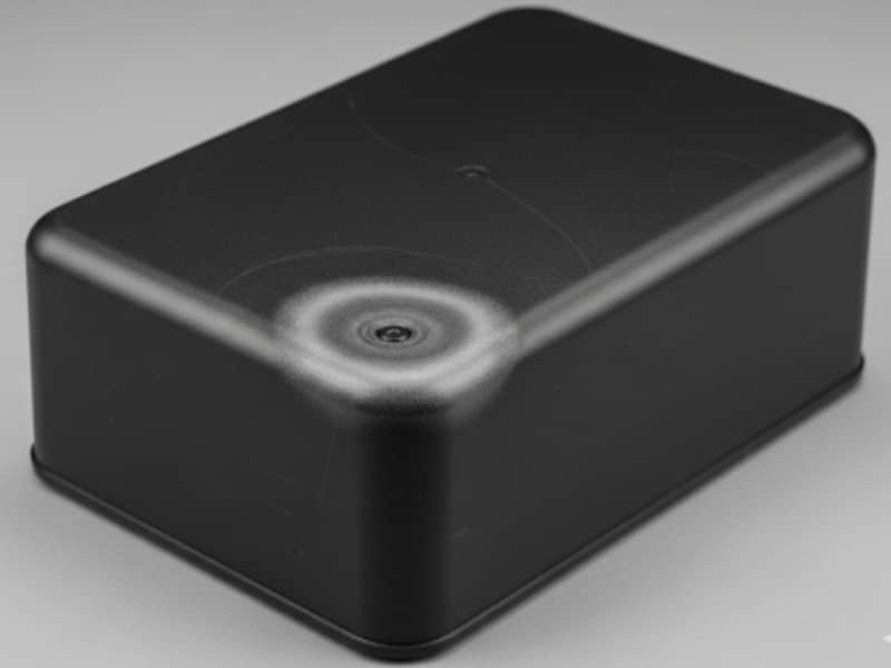
If you look closely at any injection molded part, you will almost always find a faint line running along its surface. It may appear as a slight seam, a change in texture, or sometimes a visible mark depending on the material and finish.
This line is not a defect in the traditional sense, but it often becomes a key factor in how a part looks, assembles, and performs in real applications. In some designs, it is barely noticeable. In others, it can directly affect appearance quality or even functional sealing.

Understanding where this line comes from and how it interacts with mold design is an important step in controlling both aesthetics and manufacturability in injection molded parts.
What Is a Parting Line?
Every injection molded part has a parting line, even if it is not always immediately noticeable. It is the line left on the surface where the two halves of the mold separate when the part is released.
In simple terms, a plastic part is formed inside a closed steel cavity. When it is ready to be ejected, the mold opens along a defined direction, and the interface where the two mold halves meet during this opening process naturally leaves a visible or slightly raised line on the finished part.
Types of Parting Lines in Injection Molding
In practice, a parting line is not always placed in the same way. If you start paying attention to molded products around you, you will notice that the “seam line” can appear in very different locations and forms.
Flat Parting Line
This is the most straightforward type. The mold separates along a flat, single direction, and the parting line runs around the part on one consistent plane.
You will often see this on simple geometries like boxes, covers, or symmetrical housings. From a manufacturing point of view, this type is the easiest to control, and the seam is usually predictable and uniform.
Stepped Parting Line
In more complex parts, the parting line may “step” up or down as it follows changes in the product shape. Instead of staying on one plane, it adjusts to different height levels of the part.
You can imagine it like a line that needs to climb small surfaces or drop along edges to avoid undercuts or deep features. This type is common in parts with ribs, bosses, or multi-level structures.
Curved Parting Line
For more organic or aesthetic designs, the parting line may follow a curved path along the surface of the part.
Rather than being straight or angular, it blends into natural contours to reduce visibility. This is often used in consumer products where appearance is more important than structural simplicity.
Beveled Parting Line
In some designs, the parting line is not left as a sharp step, but intentionally softened into a beveled or angled transition.
Instead of forming a clear edge, the interface between the two mold halves is slightly offset or angled. This reduces the visual contrast of the seam, making it less noticeable on the final part.
This approach is often used in consumer products where appearance is important, especially on curved surfaces or areas close to direct visual focus. While it does not eliminate the parting line, it helps make it less visually and physically prominent.

How to Control Parting Line Visibility and Quality
The visibility and quality of a parting line are not determined by a single factor. Instead, they are controlled through design decisions, mold structure, and processing stability. In practice, parting line control can be understood from three engineering perspectives.
Control Parting Line Visibility Through Placement
The first step in managing parting line appearance is deciding where it should be located on the part. Even with good mold quality, poor placement will make the line more visible in the final product.
- Place the parting line in non-cosmetic or less visible areas whenever possible
- Avoid running it across large flat or high-gloss surfaces
- Prefer edges, corners, or naturally divided geometric transitions
- Keep it away from key visual or functional surfaces
Reduce Mismatch Through Geometric Design
When design mold, The female mold and the male mold of mold must be closely matched to avoid the appearance of contour or stepped parting lines. If the parting line must be designed on the side wall of the part, the surface of the side wall of the part should be designed as shown in Figure 1 below, and the distance between the two sides is 0.254~0.381mm. Where possible, 0.254mm convex circles can be designed on the side walls, as shown in (Figure 2 below).
(Figure 1)
(Figure 2)
Since the surface of the molded part needs to be trimmed, an arc edge with a radius of 0.381~0.794mm is designed at the parting line in injection molding, as shown in Figure 3 below. Set a distance, as shown in Figure 4 below, this distance is about 1.98~2.36mm, so it is easy to remove the flash. When designing the mold clamping, try to use the rounded parting line, because the circular parting line is easier to design than the straight or deformed parting line.
(Figure 3)
 (Figure 4)
Prevent Flash and Parting Line Worsening
When sealing between mold halves is not stable, material can escape into the parting interface and create flash. This not only affects quality but also makes the parting line more visible.
- Avoid excessive injection pressure during initial filling
- Adjust holding pressure and injection time step by step
- Ensure sufficient clamping force during molding
- Check and repair worn or damaged parting surfaces
- Keep mold mating surfaces clean and well maintained
- Use trial adjustments before increasing pressure or cycle intensity
Flash control is essentially sealing control. A stable mold interface is key to keeping the parting line clean and controlled.
Conclusion
In practice, good parting line control starts early in the design stage and continues through tooling and production. If you want to better understand how part design influences manufacturability, you can also refer to our guide on injection molding design. For projects that require production support, Zhongde provides custom injection molding service to help turn design requirements into stable, production-ready parts.
If you are developing a new product and want to reduce risks related to surface quality and tooling details, feel free to contact Zhongde for practical engineering support from prototyping to mass production.