Compression mold design plays a central role in achieving efficient production of rubber and composite parts. Optimizing the design helps ensure uniform material flow, reduce defects, and improve part quality. This article explores key considerations for creating effective compression molds, providing compression molding design tips and a comprehensive guide to optimize the molding process.
What is Compression Molding?
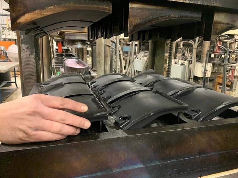
Compression molding process places pre-formed material, such as rubber blanks or composite prepregs, into an open mold cavity. The mold closes under pressure and heat, allowing the material to flow, fill the cavity, and cure.

Compression Molding Materials
Compression molding typically uses flexible rubber molding materials with excellent heat and chemical resistance, ensuring strong and precise molded parts.
- Natural Rubber (NR): Offers high elasticity and tear resistance. Used in seals and vibration dampers. Shrinkage around 1.5-2%. Requires venting to prevent voids.
- Nitrile Rubber (NBR): Resists oils and fuels. Common in automotive seals. Moderate flow and fast cure.
- Ethylene Propylene Diene Monomer (EPDM): Withstands ozone and weathering. Suitable for outdoor gaskets. Low shrinkage (1-1.5%). Handles large parts.
- Silicone Rubber: Operates in wide temperatures (-60°C to 250°C). Biocompatible for medical and food-grade items. Needs precise venting for low-viscosity types.
- Fluorocarbon Rubber (FKM/Viton): Handles chemicals and high heat. Applied in aerospace seals. Higher shrinkage (2-3%). Molds need compensation.
- Sheet Molding Compound (SMC)/Bulk Molding Compound (BMC): Glass-fiber reinforced polyester. Provides strength for automotive panels. Controls fiber orientation to avoid warpage.
- Polyurethane (PU): Resists abrasion and impact. Used in rollers. Combines with compression in cast variants.
Key Factors in Compression Mold Design
Defects in compression molding often stem from overlooked details in early designing. Experienced mold manufacturers intervene ahead to spot risks via Design for Manufacturability reviews. This prevents costly changes later. Below are several critical factors to consider when designing a compression mold:
Wall Thickness
One of the most important considerations in compression mold design is maintaining uniform wall thickness. A consistent wall thickness ensures that the material is compressed evenly, allowing for uniform heat distribution and curing. If the wall thickness is too thick in certain areas, it can lead to uneven curing, gas bubbles, or even scorching of the material, all of which negatively impact the final product.
In terms of compression molding design tips, designers should aim for a uniform wall thickness as much as possible, especially for parts with critical dimensions. This can be achieved by designing the mold cavity with even depth and flow paths to ensure smooth material distribution.
For thicker sections that cannot be avoided, designers can integrate additional mold features like localized venting or heating elements to compensate for the thicker areas and help with uniform material distribution.
Draft Angles
Unlike injection molding, which uses ejector pins to help remove the part from the mold, compression molding relies on the opening and closing direction of the mold for part ejection. To facilitate easy demolding and prevent issues such as tearing or sticking, parts should be designed with appropriate draft angles.
Rubber compression mold design should include a draft angle between 1° and 3° for ease of demolding. If a part has deep features or intricate shapes, additional mold structures, such as split molds or ejector systems, may be necessary.
Parting Line
In terms of compression molding design guidelines, it is essential to plan the parting line placement early in the design process. Ideally, the parting line should be placed on non-visible areas or, if this is not possible, it should be strategically located where it will not interfere with the part’s functionality.
When designing the mold, consider the complexity of the geometry and how the parting line can best be positioned to avoid compromising part quality. Multiple parting lines or the use of inserts may be required for complex designs to strike the right balance between function and aesthetics.
Undercuts and Complex Geometry
Undercuts and complex geometries require the use of additional mechanisms, such as movable cores or inserts, to form the part.
If undercuts or complex shapes are necessary, designers can incorporate features such as movable cores or split molds. However, it’s essential to maintain tight tolerances and ensure that any inserts or movable parts align correctly during molding to avoid misalignment or part defects.
Venting
During the compression molding process, air needs to escape from the mold cavity as the material is compressed. If air is trapped inside the mold, it can lead to defects such as burns, air pockets, or voids in the final part.
In the compression molding design guide, proper venting is highlighted as one of the most critical aspects of mold design. Venting channels should be included in strategic locations of the mold, such as at the ends of cavities or in thin-walled sections. For materials with higher viscosities, such as rubber, designers may also consider incorporating multi-stage compression or slow mold opening to allow air to escape gradually.
Material Selection
Different materials have unique properties that affect their flow, curing, and shrinkage behavior. The rubber compression mold design must take into account the material’s thermal conductivity, shrinkage rates, and viscosity. Designers should also ensure that the mold heating system is optimized for the chosen material, whether through electric heating elements, heated plates, or other methods. Additionally, material shrinkage must be accounted for in the mold design to ensure accurate part dimensions.
Insert Integration
In many applications, such as custom auto parts, compression molded parts include inserts, such as metal components or plastic elements, that need to be embedded into the final product.
To achieve this, designers should incorporate reliable positioning features into the mold, such as locating pins, grooves, or magnetic fixtures. In some cases, it may also be beneficial to preheat the inserts or apply a bonding agent to improve adhesion and reduce the likelihood of insert movement during the molding process.
Conclusion
Strong compression mold design combines sensible product geometry, expert mold engineering, and precise material-process alignment. Following these compression molding design tips avoids pitfalls and enables higher efficiency with lower scrap rates.