When looking at a part with holes, you may notice that some holes go completely through the material, while others stop at a certain depth without opening on the opposite side. These two common hole designs are known as through holes and blind holes.
Although the difference sounds simple, choosing between blind holes vs through holes can affect part design, machining processes, assembly methods, and overall performance. Understanding how these two hole types work helps designers make better decisions before manufacturing.
What Are Blind Holes and Through Holes?
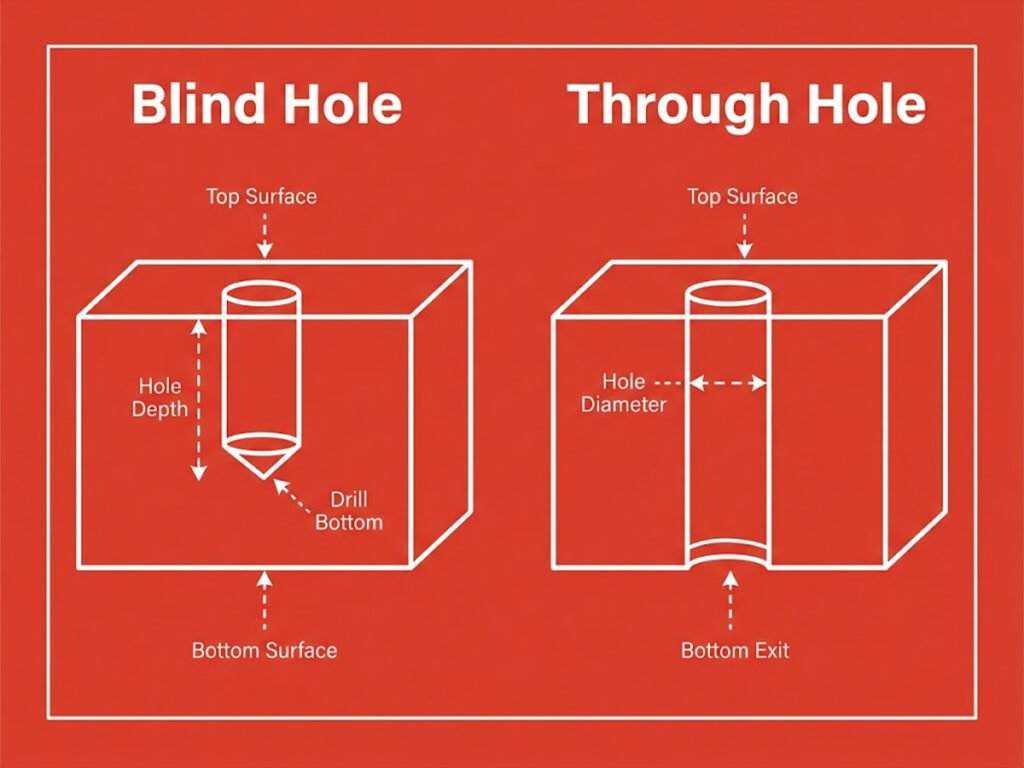
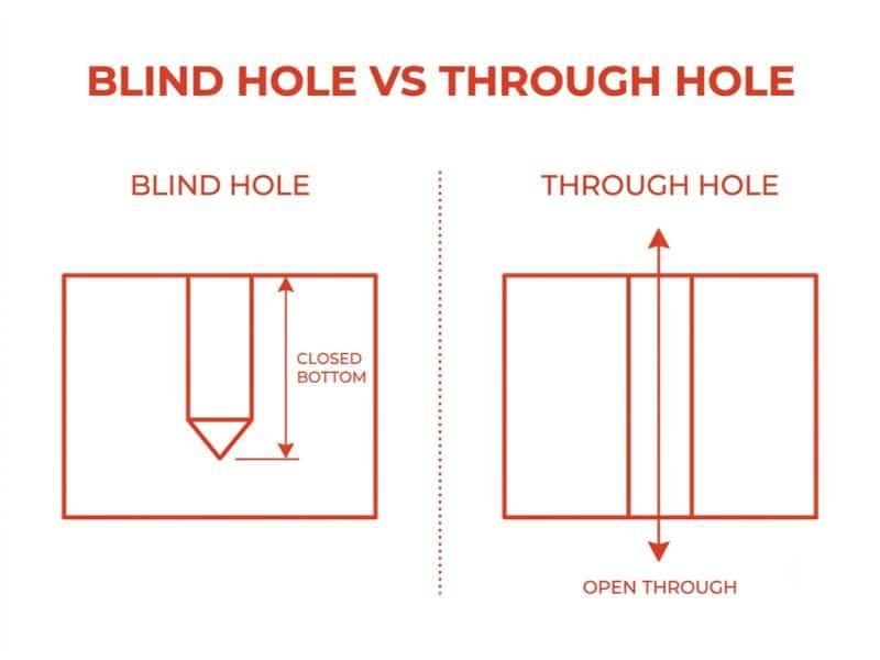
A blind hole is a hole that starts from one surface of a part but does not pass completely through the material. Instead, it has a specific depth and a closed bottom. The depth of a blind hole can be precisely controlled during machining to meet different design requirements.
A through hole is a hole that extends through the entire thickness of a part, creating an opening on both sides. Unlike a blind hole, it does not have a closed end because the cutting tool or drilling process passes completely through the material.
In simple terms, a blind hole is like a hole drilled into a wall without reaching the other side, while a through hole is like a tunnel that goes all the way through.
Blind Hole vs Through Hole: What Are the Differences?
As mentioned above, the main difference between blind holes and through holes is whether the hole extends through the entire thickness of a part. However, this structural difference also affects how the holes are machined, measured, and inspected during manufacturing.
Machining Process
The machining process for these two hole types can be different. Through holes are usually easier to machine because the cutting tool can pass completely through the material, allowing chips and cutting fluids to exit more easily. Blind holes require more control over drilling depth, tool movement, and chip removal, especially when deeper holes or tighter tolerances are needed.
Hole Bottom Geometry
A through hole has no bottom surface, while a blind hole always has a defined bottom. For example, a standard drilled blind hole usually has a conical bottom caused by the drill tip. If a flat bottom is required, additional machining operations may be necessary.
Tool Access and Design Limitations
The opening direction and depth of a hole can affect tool access during machining. Through holes generally provide better access because the tool can move through the entire part. For blind holes, the available machining depth, tool length, and internal space need to be considered to avoid issues such as tool deflection or insufficient chip removal.
Inspection Methods
The inspection process can also vary between the two designs. Through holes can often be checked from both sides, making it easier to verify diameter and alignment. Blind holes require additional measurements to confirm hole depth, bottom condition, and internal dimensions.
When to Use Blind Holes and Through Holes?
The choice between a blind hole and a through hole depends on the function of the part, assembly requirements, and design limitations. Neither hole type is universally better; the right option depends on what the component needs to achieve.
When to Use Blind Holes
Blind holes are commonly used when a hole is only needed to a specific depth or when the opposite surface of the part needs to remain intact. They are often found in components where fasteners, inserts, or locating features need to be installed without creating an opening on the other side.
For example, a threaded blind hole can be used to mount a cover or bracket to a part while keeping the back surface smooth. Blind holes are also useful when a through opening could affect the appearance, sealing performance, or structural integrity of a component.
When to Use Through Holes
Through holes are typically used when a fastener, shaft, pin, or other component needs to pass completely through the part. Because both ends of the hole are accessible, they can also simplify assembly and inspection.
For example, a bolt passing through two plates requires through holes so that the fastener can extend through both components and be secured with a nut on the opposite side. Through holes are also commonly used for drainage, ventilation, and weight reduction designs.
How to Represent Blind Holes and Through Holes in Drawings?
After deciding on the hole type, it is important to clearly communicate the design intent through technical drawings. Proper hole representation helps manufacturers understand the required depth, size, and machining requirements.
How to Draw a Through Hole
A through hole is usually shown in a standard orthographic view using two visible circles or hidden lines depending on the viewing direction. Since the hole passes through the entire part, the drawing only needs to specify the hole diameter and other required features, such as tolerances, threads, or surface finishes.
For example, a through hole may be marked as:
⌀10 THRU
This indicates that the hole has a diameter of 10 mm and extends completely through the part.
How to Draw a Blind Hole
A blind hole needs additional information because its depth is not visible from the opening. In addition to the hole diameter, the drawing should include the required hole depth and any other specifications, such as thread details or bottom requirements.
For example, a blind hole may be marked as:
⌀10 × 20 DEEP
This indicates a hole with a 10 mm diameter and a depth of 20 mm.
For threaded blind holes, the drawing may also include thread specifications and the required thread depth to ensure correct machining.
How to Drill Blind Holes and Through Holes?
Drilling is one of the most common methods for creating both blind holes and through holes. The basic cutting principle is the same: a rotating drill bit removes material to form a cylindrical hole. However, the two hole types require different control methods during drilling, especially in terms of depth, chip removal, and tool movement.
Through Holes
Through holes are relatively straightforward because the drill bit can pass completely through the workpiece.
- The first step is to secure the workpiece and align the drill bit with the required hole location. For simple drilling, this can be done with a drill guide or drill press. For precision manufacturing, CNC machining controls the tool position automatically.
- The drill bit continues cutting until it exits the opposite side of the part. Since chips can escape from the bottom opening, through holes usually have fewer chip removal issues compared with blind holes.
- The exit side of a through hole may produce burrs during drilling. Additional operations such as deburring or chamfering may be required to improve the edge condition.
Blind Holes
Blind holes require more control because the drill must stop at a specific depth without breaking through the material.
Set the Required Drilling Depth
The drilling depth must be defined before machining begins. In manual drilling, operators may use depth stops or markings on the drill bit. In CNC machining, the Z-axis movement is programmed to stop the tool at the required position.
Control Chip Removal During Drilling
Because chips cannot exit through the bottom of a blind hole, they can accumulate around the cutting edge and affect drilling performance. Peck drilling is commonly used, where the drill repeatedly retracts to remove chips and allow cutting fluid to reach the tool.
Consider the Hole Bottom Shape
A standard twist drill creates a conical bottom because of the drill point geometry. If the design requires a flat-bottom blind hole, additional machining operations such as milling or boring may be necessary.
Use Suitable Tools for Deep Blind Holes
For deeper blind holes, tool selection becomes more important. Longer drills may experience greater deflection, while insufficient cooling can accelerate tool wear. In industrial machining, coolant-through drills and optimized cutting parameters are often used to improve hole quality.
Conclusion
The right hole type depends on factors such as assembly needs, machining methods, dimensional requirements, and the working conditions of the component. With proper planning and manufacturing experience, both blind holes and through holes can be produced with reliable accuracy and quality.
At Zhongde, we provide custom machining solutions with advanced equipment and professional manufacturing support. Whether you need precision holes, complex geometries, or custom CNC machined parts, our team can help turn your designs into reliable components. Contact Zhongde today to discuss your project requirements.