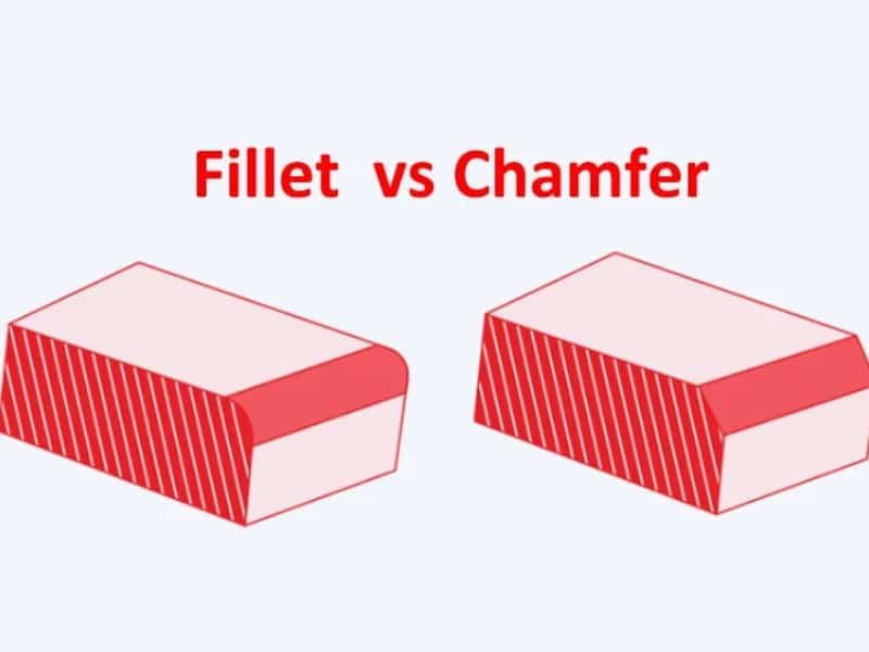
Fillet and chamfer are two common design features used at the edges where two surfaces meet. Both serve to remove sharp corners, making custom plastic parts safer and easier to handle. They also play an important role in manufacturing, assembly, and product performance by reducing stress concentrations and enhancing the overall appearance of custom parts.
Despite their similarities, fillet and chamfer have key differences. Read the following blog to explore in detail the differences between chamfer and fillet.
More info about: Plastic Part Design Guide
What is a Fillet?
In the field of mechanical design and manufacturing, fillet design refers to the use of a curved transition at the edges or corners where two surfaces meet, in order to eliminate sharp edges. Common types of fillets include external fillets, internal fillets, and transition fillets, each suited to different structural and stress requirements. In practice, fillets are typically achieved through processes such as injection molding, CNC machining, mold fabrication, or post-processing methods like polishing and grinding.

The Purpose of A Fillet Design
- Stress Reduction: Fillets help distribute stress more evenly across a part, reducing the likelihood of cracks or fractures, particularly in areas with sharp corners.
- Improved Flow: In manufacturing processes like injection molding, fillets can enhance the flow of molten material, reducing the risk of uneven filling and improving the overall quality of the molded part.
- Aesthetics: Fillets contribute to the visual appeal of a part by creating a smoother, more pleasing transition between surfaces.
What is a Chamfer?
A chamfer is a design feature that is a beveled or angled edge between two connecting surfaces of a part. It is usually creating a symmetrical V-shaped groove. This angled edge replaces a sharp corner or right angle, providing several functional and aesthetic benefits in part design and manufacturing. Chamfers are in contrast to fillets. Chamfer do not have a curved shape, it is straight and has a sharp angle. Most chamfer are at 45° or 60°, but a chamfer can be made at any angle. They are generally easier to manufacture and provide specific advantages in terms of assembly and safety.
Chamfers can be created through CNC machining, milling, or grinding for metal parts. For plastic parts, chamfer are usually incorporated into the mold and formed during molding or finished afterward.

The Purpose of A Chamfer Design
- Ease of Assembly: Chamfers are often used to facilitate the assembly of parts by providing a guide for mating components. The beveled edge makes it easier to align and join parts during the assembly process.
- Safety Improvement: Sharp corners can pose safety risks, and chamfers help mitigate these risks by reducing the likelihood of cuts or injuries when handling or assembling parts.
- Aesthetic Considerations: Chamfers contribute to the overall visual appeal of a part by introducing a beveled edge, adding a touch of sophistication to the design.
- Mating Parts Compatibility: The beveled edge created by a chamfer can increase the allowance between mating parts, improving the fit and reducing the chances of interference during assembly.
How are They Marked in The Drawing?
Drawing marking of Fillet
In engineering drawings, fillets are typically designated by “R” followed by a numerical value, for example, “R3” indicates a 3 mm radius fillet. When noting, leader lines are typically used to indicate the specific corner. If a part has multiple fillets with the same radius, a unified notation can be used in the drawing annotation, such as “All unnoted fillets are R2.” Fillets with different radii require separate notation.

Drawing marking of Chamfer
Chamfers are typically indicated on drawings using dimension × angle or double-sided dimensions. For example, “2 × 45°” indicates a chamfer with a 2 mm side and a 45° angle, while “1 × 1” indicates an equal-sided chamfer. The dimension is typically placed directly above the edge line, with a leader line pointing to the chamfer location. For multiple chamfers of the same dimension, these can be collectively described in a drawing note, and tolerances or processing requirements may be added.
When to Use a Fillet and Chamfer?
In part manufacturing, the random use of fillets and chamfers can lead to unnecessary processing costs. Understanding the differences between fillets and chamfers (fillet vs chamfer) and knowing when to use them can help reduce manufacturing costs and improve part efficiency.
Add Chamfer to the Hole
For parts with holes where screws or bolts will be inserted, a chamfer is a better choice compared with a fillet. The sharp edge of the chamfer will make smoother pin movement down the hole and easier fastener insertion.
Add Fillet to Edges of the Part
For part edges, especially when safety and stress reduction are priorities, fillets are preferred. They distribute stress, prevent sudden deformation, and eliminate sharp edges.
Add Fillet and Chamfer to Outside Edges
Both fillets and chamfers can be used on part outside edges. When the exterior edge design requirements are not high, you can choose chamfers instead of sharp corners to reduce the risk of injury during use. If your part outside edges aesthetically are important, fillets would be better. It will relieve stress and make the design look better.
Add Chamfer to Mating Parts
Chamfers are better during assembling mating parts. The hole with a chamfered design will make the movement and insertion smoother. Moreover, chamfers of different sizes can be created with one tool.
What is the Difference Between a Fillet and Chamfer?
Understanding the difference between fillet and chamfer is key in part design. Proper plastic part corner design improves stress flow, assembly fit, and manufacturability.
1. Safety
- Fillet: Rounded edges eliminate sharp corners, reducing risk of cuts and improving handling safety.
- Chamfer: Beveled edges remove sharp corners as well, mainly for guiding or edge clearance; still safe if designed properly.
2. Stress Distribution
- Fillet: Smooth transition reduces stress concentration, especially in internal corners, rib junctions, and load-bearing areas.
- Chamfer: Provides limited stress relief; suitable for non-critical edges.
3. Application
- Fillet: Used in internal corners, structural junctions, and surfaces where smooth transition, stress relief, or aesthetics are needed.
- Chamfer: Used on external edges, hole entrances, or mating surfaces to guide assembly, ease insertion, and protect edges.
4. Manufacturing Cost & Machining Time
- Fillet: Producing fillets can be more complex and time-consuming depending on the process. For metals, this could involve CNC milling, grinding, or casting/forging with a fillet radius; for plastics, molds must include the fillet design. Larger or internal fillets increase tooling complexity and cost.
- Chamfer: Easier and faster to produce across multiple manufacturing processes—milling, turning, grinding, stamping, or mold design for plastics. A single tool or mold feature can often create various chamfer sizes, making it more cost-effective.
5. Tooling Considerations
- Fillet: May require radius-specific cutters, ball-end mills, or special mold inserts depending on size and material.
- Chamfer: Standard cutting or forming tools usually suffice; less dependent on tool size.
Comparison of Design Principles of Fillet and Chamfer
Fillet Design Principles
Stress Distribution Optimization: Sharp corners at the intersection of ribs and base plates, at the bottom of holes, or at inner corners can generate high stress concentrations. Fillets, through curved surface transitions, diffuse stress along the surface, reducing local stress peaks and improving part strength and fatigue life.
Force Path Continuity: Fillets create smooth transitions in local structural stiffness, forming a continuous force path and minimizing the impact of excessive stress gradients on the overall stiffness of the part.
Interface Matching and Local Thickness Considerations: When designing fillets, consider part thickness, material elasticity, and interface matching with adjacent parts to avoid new interference or weak areas.
Plastic Molding Optimization: In plastic parts, fillets improve flow, reduce filling pressure concentrations, and minimize the risk of warpage and porosity.
Chamfer Design Principles
Edge Transition and Assembly Guidance: Chamfers create a sloped surface, making hole openings or outer edges easier to insert and position during assembly while also reducing stress at sharp corners.
Localized Stress Control: Chamfers at non-load-bearing edges reduce localized stress peaks and create clear functional boundaries, clarifying force paths and structural logic.
Geometry and Assembly Matching: The chamfer angle and width are determined by part thickness, assembly clearance, and contact surface dimensions, ensuring smooth and interference-free part insertion.
Mold Release and Manufacturing Feasibility: Chamfers improve draft angles and parting surface design in injection molded, die-cast, or milled parts, reducing machining and molding defects.
Conclusion of Fillet and Chamfer
Fillet vs. chamfer is a common consideration in part design. Zhongde provides professional guidance to clients during the product design phase, optimizing fillet and chamfer design based on part stress, assembly, and molding requirements to ensure an optimal balance between part functionality, safety, and manufacturing efficiency.