Injection molding speed is a critical parameter in modern manufacturing, directly influencing production efficiency, unit cost, and delivery timelines. For custom plastic parts, faster production often translates into shorter lead times and more competitive pricing. However, in injection molding, speed is not a single variable—it is the result of a balanced system involving product design, material behavior, mold engineering, and process control.
What Is Injection Molding Speed?
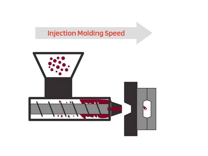
Injection molding speed refers to the velocity at which the machine screw moves forward during the filling phase. It is commonly measured in millimeters per second (mm/s) or in volumetric terms as cubic centimeters per second (cm³/s). This speed determines the flow rate of the melt front inside the runners and cavity.
The injection phase usually lasts only 1 to 5 seconds but sets the foundation for the rest of the cycle. During this short time, the molten plastic must fill every section of the cavity before it begins to cool and solidify against the mold walls.
Key Factors That Influence Required Speed
Several factors affect the injection molding speed:
- Material viscosity
- Gate size and location
- Part wall thickness
- Flow length
- Mold venting
The Importance of Injection Molding Speed
Injection molding speed is a critical process parameter that directly affects part quality, production efficiency, and manufacturing cost. It governs how quickly molten plastic fills the mold cavity, and has an impact on the final product and the overall production process.
Impact on Part Quality
Injection molding speed directly affects surface finish, mechanical properties, and dimensional accuracy. Properly controlled speeds ensure smooth surfaces, strong weld lines, uniform cavity pressure, and minimal warpage or shrinkage variation. Speeds that are too low may cause flow marks or dull surfaces, while excessively high speeds can lead to jetting, burn marks, internal stress, or weakened mechanical performance. Maintaining an optimal injection speed is essential to produce high-quality, consistent parts.
Impact on Production Efficiency and Cost
Optimized injection molding speed shortens fill time and overall cycle time, increasing throughput and reducing material waste. Lower defect rates and more consistent production reduce per-part costs, making manufacturing more competitive and profitable—especially for high-volume custom orders.
Common Defects Related to Injection Molding Speed
Many typical injection molding defects are directly connected to incorrect speed settings.
Short Shots and Incomplete Filling
Short shots occur when the melt solidifies before the cavity is completely filled. This defect is most often caused by an injection molding speed that is too low, especially in thin sections or long flow paths. Increasing speed in the early or middle stages usually resolves the issue when combined with adequate venting.
Flow Marks and Weak Weld Lines
Flow marks and weak weld lines appear when the melt front slows down or stagnates before meeting. These defects reduce both visual quality and mechanical performance. Adjusting the speed profile to maintain steady melt front velocity helps eliminate stagnation points.
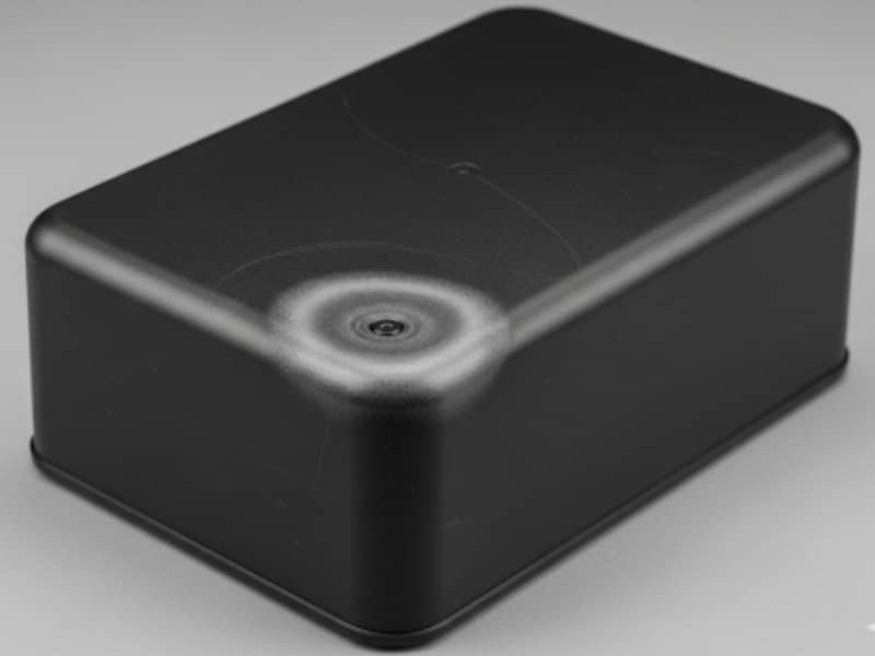
Jetting, Burn Marks, and Surface Defects
Excessively high injection molding speed can cause jetting (snake-like surface lines) and burn marks from trapped air or shear heating. These problems are common in materials sensitive to high shear, such as PC or glass-filled resins. Reducing speed in the final stage of filling often prevents these defects.
Flash and Air Traps
High speed at the end of filling can force material into parting lines or vents, resulting in flash. Air traps may also form if the melt front advances too quickly. Lowering the final-stage speed and verifying vent design usually corrects these issues.
Warpage and Sink Marks
Uneven filling caused by improper speed distribution leads to differential cooling and shrinkage, resulting in warpage or sink marks. Multi-stage injection molding speed profiles that match the part geometry help create more uniform pressure and reduce these defects.
Optimization Injection Speed
Avoid the injection molding speed-related defects and improve the molding effective, optimize injeciton molding speed is important. Multi-stage injection speed control is the most effective method for achieving high-quality filling in complex custom parts. Single-speed settings cannot accommodate variations in wall thickness, flow length, or gate location.
Use Multi-Stage Control to Optimize Injection Speed
Different sections of a part fill at different rates. Thin walls and long flow paths require faster speeds to prevent premature freezing, while thick sections or areas near the end of fill need slower speeds to avoid over-pressurization and surface defects. Dividing the screw stroke into 3 to 5 independent velocity stages allows precise control at each phase of filling, resulting in more uniform melt front advancement and better overall part quality.
Step-by-Step Optimization Process
1. Baseline Trial
Start with the same speed across all stages (for example, 60–80 mm/s). Produce short shots and increase the speed by 5% increments while recording part weight, fill percentage, and visual appearance. This step establishes the viscosity curve and identifies the stable processing window for the specific material and mold.
2. Define Stage Positions
Set transfer positions based on screw stroke percentage. A common setup uses:
- S1 at approximately 30% stroke (gate and runner area)
- S2 at 85% stroke (main cavity filling)
- S3 at 95% stroke (end of fill)
3. Typical 3-Stage Speed Profile
A practical three-stage profile tailored to most custom parts looks like this:
Stage 1 (0–30% stroke): Moderate to high speed (50–100 mm/s) to clear the gate and runner quickly and prevent freeze-off near the gate.
Stage 2 (30–85% stroke): Highest speed (80–180 mm/s, depending on material and wall thickness) for rapid and uniform filling of the main cavity. Thin-walled parts often use higher speeds in this stage (120–180 mm/s), while standard parts stay in the 80–120 mm/s range.
Stage 3 (85–95% stroke): Reduced speed (20–60 mm/s) to prevent over-pressurization, flash, and trapped air at the end of fill.
Material-specific examples:
- PP or PE: Stage 2 often set at 80–130 mm/s (good flowability).
- ABS: Stage 2 typically 70–120 mm/s to balance surface quality and strength.
- PC or glass-filled materials: Slightly higher speeds (90–150 mm/s) due to higher viscosity, but careful control is needed to avoid shear heating.
4. Fine Tuning
Adjust each stage one at a time while checking short shots and full parts. Observe surface appearance near the gate (Stage 1), main body quality (Stage 2), and end-of-fill conditions (Stage 3). Use cavity pressure sensors when available for real-time feedback on pressure peaks. Make small changes (5–10 mm/s) and verify improvements in fill balance, weld-line strength, and dimensional stability. For complex geometries with varying wall thicknesses, 4 or 5 stages may be required for better control.
Cooperate with Zhongde and Get Benefits from Injection Modeling Speed
Optimized injection molding speed delivers several practical advantages in custom production. Shorter fill times reduce overall cycle time, increasing output and supporting faster project delivery. Lower defect rates decrease material waste and scrap, while more uniform cavity pressure improves part consistency and dimensional stability. These improvements also help extend mold life by controlling peak pressures.
As a specialized custom injection molding manufacturer, Zhongde applies optimized injection molding speed for every project. By using tailored multi-stage speed profiles, material-specific data, and process monitoring, we ensure consistent quality, precise tolerances, and cost-effective production—whether for low-volume prototypes or high-volume runs.